

E32 Usermanual EN v1.30
File info: application/pdf · 31 pages · 1.72MB
E32 Usermanual EN v1.30
FCC User Manual
UserManual.wiki migration
Full PDF Document
If the inline viewer fails, it will open the original document in compatibility mode automatically. You can also open the file directly.
Ask a question about this manual
Ask about setup, troubleshooting, compatibility, parts, safety, or missing instructions. Manuals+ will review the question and use this page’s manual context to help answer it.
Extracted Text
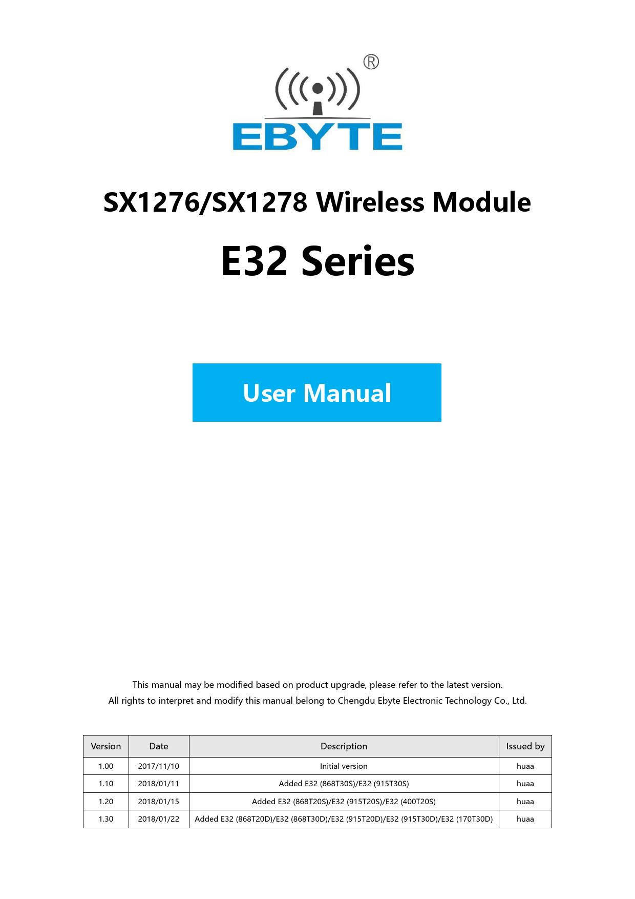
SX1276/SX1278 Wireless Module
E32 Series
User M User Manual

This manual may be modified based on product upgrade, please refer to the latest version. All rights to interpret and modify this manual belong to Chengdu Ebyte Electronic Technology Co., Ltd.

Version
1.00 1.10 1.20 1.30

Date
2017/11/10 2018/01/11 2018/01/15 2018/01/22

Description

Issued by

Initial version Added E32 (868T30S)/E32 (915T30S)

huaa huaa

Added E32 (868T20S)/E32 (915T20S)/E32 (400T20S) Added E32 (868T20D)/E32 (868T30D)/E32 (915T20D)/E32 (915T30D)/E32 (170T30D)

huaa huaa

 SX1276/SX1278 Wireless Modules
Brief Introduction

E32 Series User Manual

E32 series are UART wireless modules based on SX1276/SX1278 RF IC of SEMTECH with transparent transmission and LoRa spread spectrum technology. The modules 3.3V TTL output. SX1276/SX1278 support LoRaTM technology, The LoRaTM DSSS (direct sequence spread spectrum) technology features long range and strong anti-interference as well as strong data confidentiality. SX1276/SX1278 are considered as a milestone in terms of low speed data communication.
The modules of 30dBm transmitting power are embedded with power amplifier (PA) and low noise amplifier (LNA), which enhances the stability and longer communication range; the modules of 20dBm transmitting power adopt industrial grade crystal oscillators to ensure the stability and consistency, its precision is lower than the widely adopted 10ppm. E32 series are in stable bulk production and are widely applied in utility meters, IoT renovation, smart home, etc. The modules feature data encryption and compression. The data transmitted in air features randomness. The encryption-decryption algorithm makes data interception meaningless. And the data compression enables shorter transmitting time and lower rate of being interfered, which increased the reliability and transmitting efficiency.
E32 series strictly follow FCC, CE, CCC and such design standards and meet various RF certification requirements for exporting.

Copyright ©2012–2017, Chengdu Ebyte Electronic Technology Co., Ltd.

1

 SX1276/SX1278 Wireless Modules

Model E32 (433T20DC) E32 (433T20S) E32 (433T20S2T) E32 (433T27D) E32 (433T30D) E32 (433T30S) E32 (868T20D) E32 (868T20S) E32 (868T30D) E32 (868T30S) E32 (915T20D) E32 (915T20S) E32 (915T30D) E32 (915T30S) E32 (170T30D) E32 (400T20S)

Frequency 433M 433M 433M 433M 433M 433M 868M 868M 868M 868M 915M 915M 915M 915M 170M 470M

TX Power 20dBm 20dBm 20dBm 27dBm 30dBm 30dBm 20dBm 20dBm 30dBm 30dBm 20dBm 20dBm 30dBm 30dBm 30dBm 20dBm

Range 3000m 3000m 3000m 5000m 8000m 8000m 3000m 3000m 8000m 8000m 3000m 3000m 8000m 8000m 8000m 3000m

Packing DIP SMD SMD DIP DIP SMD DIP SMD DIP SMD DIP SMD DIP SMD DIP SMD

E32 Series User Manual
Antenna SMA-K Spring IPEX/Spring SMA-K SMA-K IPEX/Spring SMA-K IPEX/Spring SMA-K IPEX/Spring SMA-K IPEX/Spring SMA-K IPEX/Spring SMA-K IPEX/Spring

Copyright ©2012–2017, Chengdu Ebyte Electronic Technology Co., Ltd.

2

 SX1276/SX1278 Wireless Modules

E32 Series User Manual

Contents

CONTENTS ...................................................................................................................................................................................... 3

1. FEATURES............................................................................................................................................................................. 5

2. TECHNICAL PARAMETERS ............................................................................................................................................. 6

2.1. GENERAL PARAMETERS...................................................................................................................................................... 6

2.2. ELECTRICAL PARAMETERS ................................................................................................................................................ 7

2.2.1. Transmitting current ...................................................................................................................................................... 7

2.2.2. Receiving current........................................................................................................................................................... 7

2.2.3. Turn-off current ............................................................................................................................................................. 8

2.2.4. Voltage supply................................................................................................................................................................ 8

2.2.5. Communication level ..................................................................................................................................................... 9

2.3. RF PARAMETERS ............................................................................................................................................................... 9

2.3.1. Transmitting power........................................................................................................................................................ 9

2.3.2. Receiving sensitivity .................................................................................................................................................... 10

2.3.3. Recommended working frequency ............................................................................................................................... 10

2.4. TESTED RANGE ................................................................................................................................................................ 11

3. MECHANICAL CHARACTERISTICS ............................................................................................................................ 12

3.1. E32 (433T20DC)/ E32 (915T20D)/ E32 (868T20D)....................................................................................................... 12

3.1.1. Dimension.................................................................................................................................................................... 12

3.1.2. Pin definitions.............................................................................................................................................................. 12

3.2. E32 (433T20S) ................................................................................................................................................................ 13

3.2.1. Dimension.................................................................................................................................................................... 13

3.2.2. Pin definitions.............................................................................................................................................................. 13

3.3. E32 (433T20S2T)............................................................................................................................................................ 14

3.3.1. Dimension.................................................................................................................................................................... 14

3.3.2. Pin definitions.............................................................................................................................................................. 14 3.4. E32(433T27D)/ E32-TTL-1W(433T30D)/ E32 (915T30D)/ E32 (868T30D)/ E32 (170T30D) ........................... 15

3.4.1. Dimension.................................................................................................................................................................... 15

3.4.2. Pin definitions.............................................................................................................................................................. 15

3.5. E32 (433T30S)/ E32 (868T30S)/ E32 (915T30S) ........................................................................................................... 16

3.5.1. Dimension.................................................................................................................................................................... 16

3.5.2. Pin definitions.............................................................................................................................................................. 16

3.6. E32 (400T20S)/ E32 (868T20S)/ E32 (915T20S) ........................................................................................................... 17

3.6.1. Dimension.................................................................................................................................................................... 17

3.6.2. Pin definitions.............................................................................................................................................................. 17

4. RECOMMENDED CIRCUIT DIAGRAM........................................................................................................................ 18

5. FUNCTION DESCRIPTION.............................................................................................................................................. 18

5.1. FIXED MODE .................................................................................................................................................................... 18

5.2. BROADCAST MODE........................................................................................................................................................... 19

5.3. BROADCAST ADDRESS...................................................................................................................................................... 19

5.4. MONITORING ADDRESS .................................................................................................................................................... 19

5.5. MODULE RESET................................................................................................................................................................ 19

5.6. AUX DESCRIPTION .......................................................................................................................................................... 19

5.6.1. Indication of UART output .......................................................................................................................................... 19

5.6.2. Indication of wireless transmission ............................................................................................................................. 20

5.6.3. Module in configuration process ................................................................................................................................. 20

5.6.4. Notes for AUX.............................................................................................................................................................. 20

6. OPERATION MODE .......................................................................................................................................................... 21

Copyright ©2012–2017, Chengdu Ebyte Electronic Technology Co., Ltd.

3

 SX1276/SX1278 Wireless Modules

E32 Series User Manual

6.1. MODE SWITCH ................................................................................................................................................................. 21

6.2. NORMAL MODE (MODE 0) ................................................................................................................................................ 22

6.3. WAKE-UP MODE (MODE 1) ............................................................................................................................................... 22

6.4. POWER-SAVING MODE (MODE 2) ...................................................................................................................................... 22

6.5. SLEEP MODE (MODE 3) ..................................................................................................................................................... 23

7. COMMAND FORMAT ....................................................................................................................................................... 23

7.1. DEFAULT PARAMETERS .................................................................................................................................................... 23

7.1.1. Operating frequency 433MHz: .................................................................................................................................... 23

7.1.2. Operating frequency 470MHz: .................................................................................................................................... 24

7.1.3. Operating frequency 868MHz: .................................................................................................................................... 24

7.1.4. Operating frequency 915MHz: .................................................................................................................................... 24

7.1.5. Operating frequency 915MHz: .................................................................................................................................... 25

7.2. READING OPERATING PARAMETERS.................................................................................................................................. 25

7.3. READING VERSION NUMBER............................................................................................................................................. 25

7.4. RESET COMMAND ............................................................................................................................................................ 25

7.5. PARAMETER SETTING COMMAND ..................................................................................................................................... 26

8. PARAMETER SETTING.................................................................................................................................................... 28

9. PRODUCTION GUIDANCE.............................................................................................................................................. 29

9.1. REFLOW SOLDERING TEMPERATURE................................................................................................................................. 29

9.2. REFLOW SOLDERING CURVE............................................................................................................................................. 29

10. FAQ ....................................................................................................................................................................................... 30

10.1. COMMUNICATION RANGE IS TOO SHORT ........................................................................................................................... 30

10.2. MODULE IS EASY TO DAMAGE .......................................................................................................................................... 30

11. IMPORTANT DECLARATIONS....................................................................................................................................... 30

12. ABOUT US ........................................................................................................................................................................... 30

Copyright ©2012–2017, Chengdu Ebyte Electronic Technology Co., Ltd.

4

 SX1276/SX1278 Wireless Modules
1. Features

E32 Series User Manual

⚫ LoRa: The LoRa spread-spectrum means the transmitting distance is much longer than before. Confidentiality is high and the possibility of being intercepted is extremely low Strong ability of anti-interference, which has a strong inhibitory capacity for the Co-Channel Interference and all kinds of noises, and with excellent performance of anti-multipath fading
⚫ Ultra-low power consumption:
It supports WOR to reduce overall power consumption. In power-saving mode(Mode 2), it can regulate overall power consumption by setting receiving response delay; The maximum receiving response delay can be configured as 2000ms, and the average current is about 30uA.
⚫ Fixed transmission:
Module can communicate with other modules which work in different channels and addresses, it is easy for networking and repeater. For example: module A transmits AA BB CC to module B (address: 0x00 01, channel: 0x80), HEX format is 00 01 80 AA BB CC (00 01 refers to the address of module B, 80 refers to the channel of module B), then module B receives AA BB CC (only module B).
⚫ Broadcast transmission:
Set the module address as 0xFFFF, then the module can communicate with other modules in same channel.
⚫ FEC:
Forward Error Correction, high coding efficiency & good correction performance. In the case of sudden interference, it can correct the interfered data packets proactively, so that the reliability & transmission range are improved correspondingly. Without FEC, those data packets can only be dropped.
⚫ Sleep mode:
When the module works in sleep mode (mode 3), transmitting & receiving is not available, while the configuration is available. The typical current is 6.0uA in this mode.
⚫ Watchdog:
Module with a built-in watchdog, layout and precise time, once an exception occurs, the module will restart in 0.107 seconds, and will continue to work on the previous parameter Settings.
⚫ Parameter saving:
The parameters will be saved after setting and won’t be lost when powers-off. After power-up again, modules work as the previous parameters.
⚫ Meter reading:
E32 (400T20S) is optimized specifically for meter reading data logging, it supports super wide operating frequency with corresponding antenna, it also supports 197-Byte large data packet transmission.

Copyright ©2012–2017, Chengdu Ebyte Electronic Technology Co., Ltd.

5

 SX1276/SX1278 Wireless Modules
2. Technical parameters

E32 Series User Manual

2.1. General parameters

Model

Core IC

E32-TTL-100 (433T20DC) E32 (433T20S)
E32 (433T20S2T) E32 (433T27D)
E32-TTL-1W (433T30D) E32 (433T30S) E32 (868T20D) E32 (868T20S) E32 (868T30D) E32 (868T30S) E32 (915T20D) E32 (915T20S) E32 (915T30D) E32 (915T30S) E32 (170T30D) E32 (400T20S)

SX1278 SX1278 SX1278 SX1278 SX1278 SX1278 SX1276 SX1276 SX1276 SX1276 SX1276 SX1276 SX1276 SX1276 SX1278 SX1278

Size
21 * 36 mm 17*25.5mm 17 * 30 mm 24 * 43 mm 24 * 43 mm 25*40.5mm 21 * 36 mm 16 * 26mm 24 * 43 mm 25*40.5mm 21 * 36 mm 16 * 26mm 24 * 43 mm 25*40.5mm 24 * 43 mm 16 * 26mm

Net weight
6.7±0.1g 1.6±0.1g 1.6±0.1g 8.2±0.1g 8.2±0.1g 5.2±0.1g 6.7±0.1g 2.1±0.1g 8.2±0.1g 5.3±0.1g 6.7±0.1g 2.1±0.1g 8.2±0.1g 5.3±0.1g 8.2±0.1g 2.0±0.1g

Operating temperature
-40 ~ 85℃ -40 ~ 85℃ -40 ~ 85℃ -40 ~ 85℃ -40 ~ 85℃ -40 ~ 85℃ -40 ~ 85℃ -40 ~ 85℃ -40 ~ 85℃ -40 ~ 85℃ -40 ~ 85℃ -40 ~ 85℃ -40 ~ 85℃ -40 ~ 85℃ -40 ~ 85℃ -40 ~ 85℃

Operating humidity 10% ~ 90% 10% ~ 90% 10% ~ 90% 10% ~ 90% 10% ~ 90% 10% ~ 90% 10% ~ 90% 10% ~ 90% 10% ~ 90% 10% ~ 90% 10% ~ 90% 10% ~ 90% 10% ~ 90% 10% ~ 90% 10% ~ 90% 10% ~ 90%

Storage temperature
-40 ~ 125°C -40 ~ 125°C -40 ~ 125°C -40 ~ 125°C -40 ~ 125°C -40 ~ 125°C -40 ~ 125°C -40 ~ 125°C -40 ~ 125°C -40 ~ 125°C -40 ~ 125°C -40 ~ 125°C -40 ~ 125°C -40 ~ 125°C -40 ~ 125°C -40 ~ 125°C

Model
E32 (433T20DC) E32 (433T20S) E32 (433T20S2T) E32 (433T27D) E32 (433T30D) E32 (433T30S) E32 (868T20D) E32 (868T20S) E32 (868T30D) E32 (868T30S) E32 (915T20D) E32 (915T20S) E32 (915T30D) E32 (915T30S) E32 (170T30D) E32 (400T20S)

Channel (DEC)
32 32 32 32 32 32 32 32 32 32 32 32 32 32 55 116

Default Chanel (DEC)
23 23 23 23 23 23 6 6 6 6 15 15 15 15 40 60

Module Address
(DEC) 65535 65535 65535 65535 65535 65535 65536 65535 65536 65535 65536 65535 65536 65535 65535 65536

Air Data Rate (kbps)
Can be configured to 0.3, 1.2, 2.4 (default), 4.8, 9.6, 19.2 Can be configured to 0.3, 1.2, 2.4 (default), 4.8, 9.6, 19.2 Can be configured to 0.3, 1.2, 2.4 (default), 4.8, 9.6, 19.2 Can be configured to 0.3, 1.2, 2.4 (default), 4.8, 9.6, 19.2 Can be configured to 0.3, 1.2, 2.4 (default), 4.8, 9.6, 19.2 Can be configured to 0.3, 1.2, 2.4 (default), 4.8, 9.6, 19.2 Can be configured to 0.3, 1.2, 2.4 (default), 4.8, 9.6, 19.2 Can be configured to 0.3, 1.2, 2.4 (default), 4.8, 9.6, 19.2 Can be configured to 0.3, 1.2, 2.4 (default), 4.8, 9.6, 19.2 Can be configured to 0.3, 1.2, 2.4 (default), 4.8, 9.6, 19.2 Can be configured to 0.3, 1.2, 2.4 (default), 4.8, 9.6, 19.2 Can be configured to 0.3, 1.2, 2.4 (default), 4.8, 9.6, 19.2 Can be configured to 0.3, 1.2, 2.4 (default), 4.8, 9.6, 19.2 Can be configured to 0.3, 1.2, 2.4 (default), 4.8, 9.6, 19.2 Can be configured to 0.3, 0.6, 1.2, 2.4 (default), 4.8, 9.6 Can be configured to 0.3, 1.2, 2.4 (default), 4.8, 9.6, 19.2

Buffer (Byte)
512 512 512 512 512 512 512 512 512 512 512 512 512 512 512 512

SubPacket (Byte)
58 58 58 58 58 58 58 58 58 58 58 58 58 58 58 197

Copyright ©2012–2017, Chengdu Ebyte Electronic Technology Co., Ltd.

6

 SX1276/SX1278 Wireless Modules
2.2. Electrical Parameters

2.2.1. Transmitting current

Model

Min

Typ

E32 (433T20DC)

100

110

E32 (433T20S)

100

110

E32 (433T20S2T)

100

110

E32 (433T27D)

390

410

E32 (433T30D)

570

610

E32 (433T30S)

520

550

E32 (868T20D)

110

120

E32 (868T20S)

105

118

E32 (868T30D)

630

680

E32 (868T30S)

560

600

E32 (915T20D)

110

120

E32 (915T20S)

105

118

E32 (915T30D)

650

700

E32 (915T30S)

560

600

E32 (170T30D)

630

680

E32 (400T20S)

96

106

2.2.2. Receiving current

Model

Min

Typ

E32 (433T20DC)

13

14

E32 (433T20S)

13

14

E32 (433T20S2T)

13

14

E32 (433T27D)

19

20

E32 (433T30D)

19

20

E32 (433T30S)

22

23

E32 (868T20D)

13

14

E32 (868T20S)

13

14

E32 (868T30D)

24

25

E32 (868T30S)

24

25

E32 (915T20D)

13

14

E32 (915T20S)

13

14

E32 (915T30D)

20

21

E32 (915T30S)

20

21

E32 (170T30D)

21

22

E32 (400T20S)

14

15

Max 120 120 120 450 670 610 130 130 750 660 130 130 770 660 750 116
Max 15 15 15 22 22 25 15 15 26 26 15 15 22 23 23 16

E32 Series User Manual

Unit mA mA mA mA mA mA mA mA mA mA mA mA mA mA mA mA

Remarks
⚫ When designing current supply circuit, 30% margin is recommended to be remained so as to ensure longterm stable operation of the whole module;
⚫ The current at the instant of transmitting may be high, but the total energy consumed may be lower due to very short transmitting time;
⚫ When using external antenna, the impedance matching degree at different frequency points between antenna and module may affect the transmitting current value at different levels.

Unit mA mA mA mA mA mA mA mA mA mA mA mA mA mA mA mA

Remarks
⚫ The current consumed when the RF chip is only working at receiving mode is called as receiving current,the tested receiving current may be higher for some RF chips with communication protocol or the developers have loaded their own protocol to the whole module.
⚫ The current at pure receiving mode will be mA level, the users have to realize µA level receiving current through firmware development.

Copyright ©2012–2017, Chengdu Ebyte Electronic Technology Co., Ltd.

7

 SX1276/SX1278 Wireless Modules 2.2.3. Turn-off current

Model

Min

Typ

E32 (433T20DC)

3

4

E32 (433T20S)

3

4

E32 (433T20S2T)

3

4

E32 (433T27D)

4

5

E32 (433T30D)

4

5

E32 (433T30S)

4

5

E32 (868T20D)

3

4

E32 (868T20S)

3

4

E32 (868T30D)

4

5

E32 (868T30S)

4

5

E32 (915T20D)

3

4

E32 (915T20S)

3

4

E32 (915T30D)

4

5

E32 (915T30S)

4

5

E32 (170T30D)

4

5

E32 (400T20S)

3

4

Max 5 5 5 6 6 6 5 5 6 6 5 5 6 6 6 5

E32 Series User Manual

Unit µA µA µA µA µA µA µA µA µA µA µA µA µA µA µA µA

Remarks
⚫ The turn-off current means the current consumed when CPU, RAM, Clock and some registers remain operating while SoC is at very low power consumption status.
⚫ The turn-off current is always lower than the current consumed when the power supply source of the whole module is at no-load status.

2.2.4. Voltage supply

Model

Min

Typ

Max

Unit

Remarks

E32 (433T20DC)

2.3

3.3

5.2

V DC

E32 (433T20S)

2.3

3.3

5.2

V DC

E32 (433T20S2T)

2.3

3.3

5.2

V DC

E32 (433T27D)

3.3

5.0

5.2

V DC

⚫ If the voltage is at maximum value for long time, the

E32 (433T30D)

3.3

5.0

5.2

V DC

module may be damaged;

E32 (433T30S)

3.3

5.0

5.2

V DC

⚫ The power supply pin has certain surge-resistance

E32 (868T20D) E32 (868T20S)

2.3

3.3

5.2

V DC

2.3

3.3

5.2

V DC

ability, but the potential pulse higher than the maximum power supply voltage;

E32 (868T30D)

3.3

5.0

5.2

V DC

E32 (868T30S)

3.3

5.0

5.2

V DC

E32 (915T20D)

2.3

3.3

5.2

V DC

E32 (915T20S)

2.3

3.3

5.2

V DC

E32 (915T30D)

3.3

5.0

5.2

V DC

E32 (915T30S)

3.3

5.0

5.2

V DC

E32 (170T30D)

3.3

5.0

5.2

V DC

E32 (400T20S)

2.3

3.3

5.2

V DC

Copyright ©2012–2017, Chengdu Ebyte Electronic Technology Co., Ltd.

8

 SX1276/SX1278 Wireless Modules 2.2.5. Communication level

Model

Min

Typ

E32 (433T20DC)

2.5

3.3

E32 (433T20S)

2.5

3.3

E32 (433T20S2T)

2.5

3.3

E32 (433T27D)

2.5

3.3

E32 (433T30D)

2.5

3.3

E32 (433T30S)

2.5

3.3

E32 (868T20D)

2.5

3.3

E32 (868T20S)

2.5

3.3

E32 (868T30D)

2.5

3.3

E32 (868T30S)

2.5

3.3

E32 (915T20D)

2.5

3.3

E32 (915T20S)

2.5

3.3

E32 (915T30D)

2.5

3.3

E32 (915T30S)

2.5

3.3

E32 (170T30D)

2.5

3.3

E32 (400T20S)

2.5

3.3

2.3. RF Parameters

2.3.1. Transmitting power

Model

Min

Typ

E32 (433T20DC)

19.0

20.0

E32 (433T20S)

19.0

20.0

E32 (433T20S2T)

19.0

20.0

E32 (433T27D)

26.8

27.0

E32 (433T30D)

29.5

30.0

E32 (433T30S)

29.5

30.0

E32 (868T20D) E32 (868T20S) E32 (868T30D) E32 (868T30S) E32 (915T20D) E32 (915T20S) E32 (915T30D) E32 (915T30S) E32 (170T30D) E32 (400T20S)

19.3

20.0

19.0

20.0

29.4

30.0

29.5

30.0

19.3

20.0

19.0

20.0

29.4

30.0

29.5

30.0

29.4

30.0

19.0

20.0

Max 3.6 3.6 3.6 3.6 3.6 3.6 3.6 3.6 3.6 3.6 3.6 3.6 3.6 3.6 3.6 3.6
Max 20.4 20.4 20.4 28.0 30.5 30.5 20.6 20.4 30.8 30.5 20.6 20.4 30.8 30.5 30.8 20.4

E32 Series User Manual

Unit V DC V DC V DC V DC V DC V DC V DC V DC V DC V DC V DC V DC V DC V DC V DC V DC

Remarks
⚫ If the communication level is higher than the allowed maximum value, the module may be damaged;
⚫ Although the communication level can be switched with various methods, the power consumption of the whole module will be affected at great degree.
⚫ Modules are compatible with some of the microcontrollers at 5V communication level. They are too many to be listed here. Please base on practical test or talk to us for more information.

Unit dBm dBm dBm dBm dBm dBm dBm dBm dBm dBm dBm dBm dBm dBm dBm dBm

Remarks
⚫ Due to the error of the materials, each LRC component has ±0.1% error, so error accumulation will occur since multiple LRC components are used in the whole RF circuit, and the transmitting currents will be different at different modules;
⚫ The power consumption can be lowered by lowering the transmitting power, but the efficiency of the internal PA will be decreased by lowering transmitting power due to various reasons;
⚫ The transmitting power will be lowered by lowering the power supply voltage.

Copyright ©2012–2017, Chengdu Ebyte Electronic Technology Co., Ltd.

9

 SX1276/SX1278 Wireless Modules 2.3.2. Receiving sensitivity

Model

Typ

E32 (433T20DC)

-144.0

E32 (433T20S)

-144.0

E32 (433T20S2T)

-144.0

E32 (433T27D)

-145.0

E32 (433T30D)

-145.0

E32 (433T30S)

-145.0

E32 (868T20D) E32 (868T20S) E32 (868T30D) E32 (868T30S)

-144.0 -144.0 -145.0 -145.0

E32 (915T20D)

-144.0

E32 (915T20S) E32 (915T30D) E32 (915T30S) E32 (170T30D) E32 (400T20S)

-144.0 -145.0 -145.0 -145.0 -144.0

Max -146.0 -146.0 -146.0 -147.0 -147.0 -147.0 -146.0 -146.0 -147.0 -147.0 -146.0 -146.0 -147.0 -147.0 -147.0 -146.0

E32 Series User Manual

Unit -147.0 -147.0 -147.0 -148.0 -148.0 -148.0 -147.0 -147.0 -148.0 -148.0 -147.0 -147.0 -148.0 -148.0 -148.0 -147.0

Remarks
⚫ The sensitivity is tested under the air data rate 0.3kbps,coding rate of 4/5 and spreading factor of 12;
⚫ Due to the error of the materials, each LRC component has ±0.1% error, so error accumulation will occur since multiple LRC components are used in the whole RF circuit, and the transmitting currents will be different at different modules;
⚫ The receiving sensitivity will be reduced and communication range will be shortened while increasing the air data rate.

2.3.3. Recommended working frequency

Model

Min

Typ

Max

Unit

Remarks

E32 (433T20DC)

410

433

441

MHz

E32 (433T20S)

410

433

441

MHz

E32 (433T20S2T)

410

433

441

MHz

E32 (433T27D)

410

433

441

MHz

E32 (433T30D)

410

433

441

MHz

E32 (433T30S)

410

433

441

MHz

E32 (868T20D)

862

868

893

MHz

⚫ To work within the recommended frequency can

E32 (868T20S)

862

868

893

MHz

assure the modules to meet all the parameters

E32 (868T30D)

862

868

893

MHz

⚫ To avoid the crowded integral frequency like

E32 (868T30S)

862

868

893

MHz

433.0MHz、868.0MHz、915MHz etc. is advisable.

E32 (915T20D)

900

915

931

MHz

E32 (915T20S)

900

915

931

MHz

E32 (915T30D)

900

915

931

MHz

E32 (915T30S)

900

915

931

MHz

E32 (170T30D)

160

170

173.5

MHz

E32 (400T20S)

410

470

525

MHz

Copyright ©2012–2017, Chengdu Ebyte Electronic Technology Co., Ltd.

10

 SX1276/SX1278 Wireless Modules
2.4. Tested range

Model E32 (433T20DC) E32 (433T20S) E32 (433T20S2T) E32 (433T27D) E32 (433T30D) E32 (433T30S) E32 (868T20D) E32 (868T20S) E32 (868T30D) E32 (868T30S) E32 (915T20D) E32 (915T20S) E32 (915T30D) E32 (915T30S) E32 (170T30D) E32 (400T20S)

Min 2700 2700 2700 4500 7200 7200 2700 1800 7200 7200 2700 1800 7200 7200 7200 2700

Typ 3000 3000 3000 5000 8000 8000 3000 2000 8000 8000 3000 2000 8000 8000 8000 3000

Max 3300 3300 3300 5500 8800 8800 3300 2200 8800 8800 3300 2200 8800 8800 8800 3300

E32 Series User Manual

Unit m m m m m m m m m m m m m m m m

Remarks
⚫ The external antenna used is of 5dBi gain and vertical polarization. The height is 2.5 meters;
⚫ The interval between each data packet is 2s, sending 100 packets with 30 bytes in each packet, the range at data lose rate of lower than 5% is valid range;
⚫ In order to obtain meaningful and reproducible results, we conducted the tests under in clear weather with little electromagnetic interference at suburb areas;
⚫ Distance may be shorter with interference or obstacles.

Copyright ©2012–2017, Chengdu Ebyte Electronic Technology Co., Ltd.

11

 SX1276/SX1278 Wireless Modules
3. Mechanical Characteristics
3.1. E32 (433T20DC)/ E32 (915T20D)/ E32 (868T20D)
3.1.1. Dimension

E32 Series User Manual

3.1.2. Pin definitions

Pin No.

Pin

Pin direction

Application

Input

Work with M1 & decide the four operating modes;

1

M0

(weak pull-up) Floating is not allowed, can be ground.

Input

Work with M0 & decide the four operating modes;

2

M1

(weak pull-up) Floating is not allowed, can be ground.

3

RXD

Input

TTL UART inputs, connects to external TXD output pin; Can be configured as open-drain or pull-up input.

4

TXD

Output

TTL UART outputs, connects to external RXD input pin Can be configured as open-drain or push-pull output

5

AUX

Output

To wake up the external MCU, during the procedure of self-check initialization, the pin outputs low level; Can be configured as open-drain output or push-pull output; Floating is allowed.

6

VCC

Input

Voltage positive reference of module; Power supply 2.3V ~ 5.2V DC

7

GND

Input

Ground

8

Fixing hole

Fixing hole

9

Fixing hole

Fixing hole

10

Fixing hole

Fixing hole

Copyright ©2012–2017, Chengdu Ebyte Electronic Technology Co., Ltd.

12

 SX1276/SX1278 Wireless Modules
3.2. E32 (433T20S)
3.2.1. Dimension

E32 Series User Manual

3.2.2. Pin definitions

Pin No. 1 2 3 4
5
6 7 8 9 10 11

Pin M0 M1 RXD TXD
AUX
VCC GND GND ANT GND GND

Pin direction

Application

Input

Work with M1 & decide the four operating modes.

(weak pull-up) Floating is not allowed, can be ground.

Input

Work with M0 & decide the four operating modes.

(weak pull-up) Floating is not allowed, can be ground.

Input

TTL UART inputs, connects to external TXD output pin. Can be configured as open-drain or pull-up input;

Output

TTL UART outputs, connects to external RXD input pin. Can be configured as open-drain or push-pull output

To indicate module working status

Output

To wake up the external MCU, during the procedure of self-check initialization, pin outputs low level. Can be configured as open-drain output or push-pull output

Floating is allowed

Input

Voltage reference of module Power supply 2.3V ~ 5.5V DC

Input

Ground

Output

Reference places of high frequency signal output

Output

Antenna interface (high frequency signal output)

Input Input

Ground Ground

Copyright ©2012–2017, Chengdu Ebyte Electronic Technology Co., Ltd.

13

 SX1276/SX1278 Wireless Modules
3.3. E32 (433T20S2T)
3.3.1. Dimension

E32 Series User Manual

3.3.2. Pin definitions Pin No. Pin Pin direction

Application

Input

Work with M1 & decide the four operating modes.

1

M0

(weak pull-up) Floating is not allowed, can be ground.

Input

Work with M0 & decide the four operating modes.

2

M1

(weak pull-up) Floating is not allowed, can be ground.

3

RXD

Input

TTL UART inputs, connects to external TXD output pin. Can be configured as open-drain or pull-up input;

4

TXD

Output

TTL UART outputs, connects to external RXD input pin. Can be configured as open-drain or push-pull output

5

AUX

Output

To indicate module working status To wake up the external MCU, during the procedure of self-check initialization, pin outputs low level. Can be configured as open-drain output or push-pull output Floating is allowed

6

VCC

7

GND

8

ANT

9

GND

Input
Input Output Output

Voltage reference of module Power supply 2.3V ~ 5.2V DC Ground Antenna interface (high frequency signal output) Reference places of high frequency signal output

10

GND

Input

Ground

11

GND

Input

Ground

Copyright ©2012–2017, Chengdu Ebyte Electronic Technology Co., Ltd.

14

 SX1276/SX1278 Wireless Modules

E32 Series User Manual

3.4. E32(433T27D)/ E32-TTL-1W(433T30D)/ E32 (915T30D)/ E32 (868T30D)/ E32 (170T30D)
3.4.1. Dimension

3.4.2. Pin definitions

Pin No.

Pin

Pin direction

Application

Input

Work with M1 & decide the four operating modes.

1

M0

(weak pull-up) Floating is not allowed, can be ground.

Input

Work with M0 & decide the four operating modes.

2

M1

(weak pull-up) Floating is not allowed, can be ground.

3

RXD

Input

TTL UART inputs, connects to external TXD output pin. Can be configured as open-drain or pull-up input;

4

TXD

Output

TTL UART outputs, connects to external RXD input pin. Can be configured as open-drain or push-pull output

To indicate module working status

5

AUX

Output

To wake up the external MCU, during the procedure of self-check initialization, the pin outputs low level. Can be configured as open-drain output or push-pull output

Floating is allowed

6

VCC

Input

Voltage reference of module Power supply 3.3V ~ 5.2V DC

7

GND

Input

Ground

8

Fixing hole

Fixing hole

9

Fixing hole

Fixing hole

10

Fixing hole

Fixing hole

11

Fixing hole

Fixing hole

Copyright ©2012–2017, Chengdu Ebyte Electronic Technology Co., Ltd.

15

 SX1276/SX1278 Wireless Modules
3.5. E32 (433T30S)/ E32 (868T30S)/ E32 (915T30S)
3.5.1. Dimension

E32 Series User Manual

3.5.2. Pin definitions

Pin No.

Pin

1

M0

2

M1

Pin direction Input
(weak pull-up) Input
(weak pull-up)

3

RXD

Input

4

TXD

Output

Application Work with M1 & decide the four operating modes. Floating is not allowed, can be ground. Work with M0 & decide the four operating modes. Floating is not allowed, can be ground. TTL UART inputs, connects to external TXD output pin. Can be configured as open-drain or pull-up input. TTL UART outputs, connects to external RXD input pin.
Can be configured as open-drain or push-pull output

To indicate module working status & wakes up the external MCU. During the

5

AUX

Input

procedure of self-check initialization, the pin outputs low level. Can be configured as

open-drain output or push-pull output (floating is allowed).

6

VCC

Input

Voltage reference of module. Power supply 3.3V ~ 5.2V DC

7

GND

Input

Ground

8

RESET

Input

Reset pin when program is loading(floating,users do not need to connect)

9

GND

Input

Ground pin when program is loading (floating,users do not need to connect)

10

SWIM

Input

SWIM pin when program is loading (floating,users do not need to connect)

11

+3.3V

Input

Power supply pin when program is loading (floating,users do not need to connect)

12

PB3

Input / Output NC pin,need to be floating,not connected(for further development)

13

PB1

Input / Output NC pin,need to be floating,not connected(for further development)

14

PB0

Input / Output NC pin,need to be floating,not connected(for further development)

15

GND

Ground

16

GND

Ground

17

GND

Ground

18

ANT

Output

Antenna connector (high level output, 50 characteristic impedance)

Copyright ©2012–2017, Chengdu Ebyte Electronic Technology Co., Ltd.

16

 SX1276/SX1278 Wireless Modules
3.6. E32 (400T20S)/ E32 (868T20S)/ E32 (915T20S)
3.6.1. Dimension

E32 Series User Manual

3.6.2. Pin definitions

Pin No. Pin

Pin direction

Application

1

GND

Ground

2

GND

Ground

3

GND

Ground

4

GND

Ground

Input

Work with M1 & decide the four operating modes.

5

M0

(weak pull-up) Floating is not allowed, can be ground.

Input

Work with M0 & decide the four operating modes.

6

M1

(weak pull-up) Floating is not allowed, can be ground.

7

RXD

Input

TTL UART inputs, connects to external TXD output pin. Can be configured as open-drain or pull-up input.

8

TXD

Output

TTL UART outputs, connects to external RXD input pin. Can be configured as open-drain or push-pull output

To indicate module working status & wakes up the external MCU. During the procedure

9

AUX

Output

of self-check initialization, the pin outputs low level. Can be configured as open-drain

output or push-pull output (floating is allowed).

10

VCC

Voltage reference of module. Power supply 2.3V ~ 5.2V DC

11

GND

Ground

12

NC

13

GND

Ground

14

NC

15

NC

16

NC

Input / Output

17

NC

Input / Output

18

NC

Input / Output

19

GND

Ground

20

GND

Ground

21

ANT

Output

Antenna

22

GND

Ground

Copyright ©2012–2017, Chengdu Ebyte Electronic Technology Co., Ltd.

17

 SX1276/SX1278 Wireless Modules
4. Recommended circuit diagram

E32 Series User Manual

No.

Description(STM8L MCU)

1

The UART module is TTL level. Please connect to MCU of TTL level.

2

For some MCU works at 5VDC, it may need to add 4-10K pull-up resistor for the TXD & AUX pin.

5. Function description
5.1. Fixed mode

Copyright ©2012–2017, Chengdu Ebyte Electronic Technology Co., Ltd.

18

 SX1276/SX1278 Wireless Modules
5.2. Broadcast mode

E32 Series User Manual

5.3. Broadcast address
⚫ i.e.: set the address of module A as 0xFFFF or 0x0000 and channel as 0x04. ⚫ When set A as transmitter (same mode, transparent transmission on), all modules with channel 0x04 will receive data, so as to realize
broadcast.
5.4. Monitoring address
⚫ i.,e.: set the address of module A as 0xFFFF or 0x0000 and channel as 0x04. ⚫ When set A as receiver, it will receive the data transmitted by modules with channel 0x04, so as to realize monitoring,
5.5. Module reset
⚫ When the module is powered on, AUX outputs low level immediately, conducts hardware self-check and sets the operating mode on the basis of the user parameters. During the process, the AUX keeps low level. After the process completed, the AUX outputs high level and starts to work as per the operating mode combined by M1 and M0. Therefore, the user needs to wait the AUX rising edge as the starting point of module’s normal work.
5.6. AUX description
⚫ AUX Pin can be used as indication for wireless send & receive buffer and self-check. It can indicate whether there are data that are yet to send via wireless way, or whether all wireless data has been sent through UART, or whether the module is still in the process of self-check initialization.
5.6.1. Indication of UART output ⚫ Used to wake up the external MCU

Copyright ©2012–2017, Chengdu Ebyte Electronic Technology Co., Ltd.

19

 SX1276/SX1278 Wireless Modules

E32 Series User Manual

5.6.2. Indication of wireless transmission

⚫ Buffer (empty): the internal 512 bytes data in the buffer are written to the RFIC (auto sub-packing).

⚫ When AUX=1, the user can input data less than 512 bytes continuously without overflow. when AUX=0, the internal 512 bytes data

in the buffer have not been written to the RFIC completely. If the user starts to transmit data at this circumstance, it may cause

overtime when the module is waiting for the user data, or transmitting wireless sub package.

⚫ Notes: When AUX = 1, it does not mean that all the UART data of the module have been transmitted already, perhaps the last packet

of data is still in transmission

5.6.3. Module in configuration process Only happened when power-on resetting or exiting sleep mode.

5.6.4. Notes for AUX ⚫ For function 1 & function 2 mentioned above, the priority should be given to the one with low level output, which means if it meets
each of any low level output condition, AUX outputs low level, if none of the low level condition is met, AUX outputs high level. ⚫ When AUX outputs low level, it means the module is busy & cannot conduct operating mode checking. Within 1ms since AUX
outputs high level, the mode switch will be completed. ⚫ After switching to new operating mode, it won’t be work in the new mode immediately until AUX rising edge 2ms later. If AUX is
on the high level, the operating mode switch can be effected immediately. ⚫ When the user switches to other operating modes from mode 3 (sleep mode) or it’s still in reset process, the module will reset user
parameters, during which AUX outputs low level.

Copyright ©2012–2017, Chengdu Ebyte Electronic Technology Co., Ltd.

20

 SX1276/SX1278 Wireless Modules
6. Operation Mode

E32 Series User Manual

Contents in below table are the introduction of input status of M1 & M0 and their corresponding mode:

Mode(0-3) M0 M1

Mode introduction

Remark

Mode 0 Normal

UART and wireless channel are open, transparent The receiver must work in mode

0

0

transmission is on

0 or mode 1

UART and wireless channel are open. The difference between

Mode 1 Wake-up

normal mode and wake-up mode is it will add preamble The receiver can work in mode 0,

1

0

code automatically before data packet transmission so that mode 1 or mode 2

it can awaken the receiver works in mode 2

Mode 2 0
Power-saving

1, the transmitter must work in

UART is disabled. Wireless module works at WOR mode

mode 1

1

(wake on radio). It will open the UART and transmit data after

2, transmitting is not allowed in

receiving the wireless data

this mode

Mode 3 Sleep

1

1

Parameter setting

See more in operating parameter

6.1. Mode switch

⚫ The user can decide the operating mode by the combination of M1 and M0. The two GPIO of MCU can be used to switch mode. After modifying M1 or M0, it will start to work in new mode 1ms later if the module is free. If there are any serial data that are yet to finish wireless transmitting, it will start to work in new mode after the UART transmitting finished. After the module receives the wireless data & transmits the data through serial port, it will start to work in new mode after the transmitting finished. Therefore, the mode-switch is only valid when AUX outputs 1, otherwise it will delay.
⚫ For example, in mode 0 or mode 1, if the user inputs massive data consecutively and switches operating mode at the same time, the mode-switch operation is invalid. New mode checking can only be started after all the user’s data process completed. It is recommended to check AUX pin out status and wait 2ms after AUX outputs high level before switching the mode.
⚫ If the module switches from other modes to stand-by mode, it will work in stand-by mode only after all the remained data process completed. The feature can be used to save power consumption. For example, when the transmitter works in mode 0, after the external MCU transmits data “12345”, it can switch to sleep mode immediately without waiting the rising edge of the AUX pin, also the user’s main MCU will go dormancy immediately. Then the module will transmit all the data through wireless transmission & go dormancy 1ms later automatically, which reduces MCU working time & save power.
⚫ Likewise, this feature can be used in any mode-switch. The module will start to work in new mode within 1ms after completing present mode task, which enables the user to omit the procedure of AUX inquiry and switch mode swiftly. For example, when switching from transmitting mode to receiving mode, the user MCU can go dormancy before mode-switch, using external interrupt function to get AUX change so that the mode-switch can be realized.
⚫ This operation is very flexible and efficient. It is totally designed on the basis of the user MCU’s convenience, at the same time the work load and power consumption of the whole system have been reduced and the efficiency of whole system is largely improved.

Copyright ©2012–2017, Chengdu Ebyte Electronic Technology Co., Ltd.

21

 SX1276/SX1278 Wireless Modules
6.2. Normal mode (mode 0)

E32 Series User Manual

When M1 = 0 & M0 = 0, module works in mode 0

Transmitting

The module can receive the user data via serial port, and transmit wireless data package of 58 bytes. When the data inputted by user is up to 58 byte, the module will start wireless transmission. During which the user can input data continuously for transmission. When the required transmission bytes are less than 58 bytes, the module will wait 3-byte time and treat it as data termination unless continuous data inputted by user. Then the module will transmit all the data through wireless channel. When the module receives the first data packet from user, the AUX outputs low level. After all the data are transmitted into RF chip and transmission start , AUX outputs high level. At this time, it means that the last wireless data package transmission is started, which enables the user to input another 512 bytes continuously. The data package transmitted from the module working in mode 0 can only be received by the module working in mode 0 or 1.

Receiving

The wireless receiving function of the module is on, the data packet transmitted from the module working in mode 0 & mode 1 can be received. After the data packet is received, the AUX outputs low level, 5ms later the module starts to transmit wireless data through serial port TXD pin. After all the wireless data have been transmitted via serial port, the AUX outputs high level.

6.3. Wake-up mode (mode 1)

When M1 = 0 & M0 = 1, module works in mode 1

Transmitting Receiving

The condition of data packet transmission & AUX function is the same as mode 0. The only difference is that the module will add preamble code before each data packet automatically. The preamble code length depends on the wake-up time set in the user parameters. The purpose of the preamble code is waking up the receiving module works in mode 2. Therefore, the data package transmitted from mode 1 can be received by mode 0, mode1 and mode 2.
The same as that in mode 0.

6.4. Power-saving mode (mode 2)

When M1 = 1 & M0 = 0, module works in mode 2

Transmitting

UART is closed, the module cannot receive any serial port data from outside MCU. Hence the function of wireless transmission is not available for the module working in this mode.

Receiving

In mode 2, it is required the data transmitter works in mode 1. The wireless module monitors the preamble code at regular time. Once it gets the preamble code, it will remain as receiving status and waiting for the completion of receiving the entire valid data package. Then the AUX outputs low level, 5ms later the serial port is open to transmit received wireless data through TXD. Finally, AUX outputs high level after process completed. The wireless module stays in “power-saving – monitoring” working status (polling). By setting different wake-up time, the module will have different receiving response delay (2s in maximum) and average power consumption (30uA in minimum). The user needs to achieve a balance between communication delay time & average power consumption.

Copyright ©2012–2017, Chengdu Ebyte Electronic Technology Co., Ltd.

22

 SX1276/SX1278 Wireless Modules
6.5. Sleep mode (mode 3)

E32 Series User Manual

When M1=1, M0=1, module works in mode 3

Transmitting

N/A

Receiving Parameter setting
Notes

N/A
This mode can be used for parameter setting. It uses serial port 9600 & 8N1 to set module working parameters through specific instruction format. (pls refer to parameters setting for details) When the mode changes from stand-by mode to others, the module will reset its parameters, during which the AUX keeps low level and then outputs high level after reset completed. It is recommended to check the AUX rising edge for user.

7. Command format

In sleep mode(Mode 3:M1=1, M0=1), it supports below instructions on list.

(Only support 9600 and 8N1 format when setting)

No.

Instruction format

Illustration

C0 + 5 bytes working parameters are sent in hexadecimal format. 6 bytes in total and

1

C0 + working parameters

must be sent in succession.

( Save the parameters when power-down )

Three C1 are sent in hexadecimal format. The module returns the saved parameters and

2

C1+C1+C1

must be sent in succession.

C2 + 5 bytes working parameters are sent in hexadecimal format. 6 bytes in total and

3

C2 + working parameters

must be sent in succession. ( Do not save the parameters when power-down )

Three C3 are sent in hexadecimal format. The module returns the version information

4

C3+C3+C3

and they must be sent in succession.

Three C4 are sent in hexadecimal format. The module will reset one time and they must

5

C4+C4+C4

be sent in succession.

7.1. Default parameters
7.1.1. Operating frequency 433MHz:

Model
E32-TTL-100 (433T20DC)

Frequency 433MHz

Address 0x0000

Default parameter values:C0 00 00 1A 17 44

Channel

Air data rate

Baud rate

0x17

2.4kbps

9600

Model E32 (433T20S)

Frequency 433MHz

Address 0x0000

Default parameter values:C0 00 00 1A 17 44

Channel

Air data rate

Baud rate

0x17

2.4kbps

9600

Parity 8N1
Parity 8N1

型号 Model E32 (433T120S2)

Frequency 433MHz

Address 0x0000

Default parameter values:C0 00 00 1A 17 44

Channel

Air data rate

Baud rate

0x17

2.4kbps

9600

Copyright ©2012–2017, Chengdu Ebyte Electronic Technology Co., Ltd.

Parity 8N1

Transmitting power 100mW
Transmitting power 100mW
Transmitting power 100mW 23

 SX1276/SX1278 Wireless Modules

E32 Series User Manual

Model E32 (433T27D)

Frequency 433MHz

Address 0x0000

Default parameter values:C0 00 00 1A 17 44

Channel

Air data rate

Baud rate

0x17

2.4kbps

9600

Parity 8N1

Transmitting power 500mW

Model

Frequency

Address

E32 (433T30D)

433MHz

0x0000

7.1.2. Operating frequency 470MHz:

Model

Frequency

Address

E32 (400T20S)

470MHz

0x0000

7.1.3. Operating frequency 868MHz:

Model E32 (868T20S)

Frequency 868MHz

Address 0x0000

Default parameter values:C0 00 00 1A 17 44

Channel

Air data rate

Baud rate

0x17

2.4kbps

9600

Default parameter values:C0 00 00 1A aC 44

Channel

Air data rate

Baud rate

0xaC

2.4kbps

9600

Default parameter values:C0 00 00 1A 06 40

Channel

Air data rate

Baud rate

0x06

2.4kbps

9600

Parity 8N1
Parity 8N1
Parity 8N1

Transmitting power 1W
Transmitting power 20dBm
Transmitting power 100mW

Model E32 (868T20D)

Frequency 868MHz

Address 0x0000

Default parameter values:C0 00 00 1A 06 44

Channel

Air data rate

Baud rate

0x06

2.4kbps

9600

Parity 8N1

Transmitting power 100mW

Model E32 (868T30D)

Frequency 868MHz

Address 0x0000

Default parameter values:C0 00 00 1A 06 44

Channel

Air data rate

Baud rate

0x06

2.4kbps

9600

Parity 8N1

Transmitting power 1W

Model

Frequency

Address

E32 (868T30S)

868MHz

0x0000

7.1.4. Operating frequency 915MHz:

Model E32 (915T20S)

Frequency 915MHz

Address 0x0000

Default parameter values:C0 00 00 1A 06 44

Channel

Air data rate

Baud rate

0x06

2.4kbps

9600

Default parameter values:C0 00 00 1A 0F 44

Channel

Air data rate

Baud rate

0x0F

2.4kbps

9600

Parity 8N1
Parity 8N1

Transmitting power 1W
Transmitting power 100mW

Model E32 (915T20D)

Frequency 915MHz

Address 0x0000

Default parameter values:C0 00 00 1A 0F 44

Channel

Air data rate

Baud rate

0x0F

2.4kbps

9600

Parity 8N1

Transmitting power
100mW

Model E32 (915T30D)

Frequency 915MHz

Address 0x0000

Default parameter values:C0 00 00 1A 0F 44

Channel

Air data rate

Baud rate

0x0F

2.4kbps

9600

Copyright ©2012–2017, Chengdu Ebyte Electronic Technology Co., Ltd.

Parity 8N1

Transmitting power 1W
24

 SX1276/SX1278 Wireless Modules

E32 Series User Manual

Model

Frequency

Address

E32 (915T30S)

915MHz

0x0000

7.1.5. Operating frequency 915MHz:

Model E32 (170T30D)

Frequency 170MHz

Address 0x0000

Default parameter values:C0 00 00 1A 0F 44

Channel

Air data rate

Baud rate

0x0F

2.4kbps

9600

Default parameter values:C0 01 0A 1A 0A 44

Channel

Air data rate

Baud rate

0x28

2.4kbps

9600

Parity 8N1
Parity 8N1

Transmitting power 1W
Transmitting power 1W

7.2. Reading operating parameters

Instruction format C1+C1+C1

Description In sleep mode(M0=1,M1=1), User gives the module instruction (HEX format): C1 C1 C1, Module returns the present configuration parameters. For example, C2 00 00 1A 17 44.

7.3. Reading version number

Instruction format C3+C3+C3

Description In sleep mode(M0=1,M1=1), User gives the module instruction (HEX format): C3 C3 C3, Module returns its present version number, for example C3 32 xx yy. 32 here means the module model (E32 series); xx is the version number and yy refers to the other module features.

7.4. Reset command

Instruction format C4+C4+C4

Description In sleep mode(M0=1,M1=1), User gives the module instruction (HEX format): C4 C4 C4, the module resets for one time. During the reset process, the module will conduct self-check, AUX outputs low level. After reset completing, the AUX outputs high level, then the module starts to work regularly which the working mode can be switched or be given another instruction.

Copyright ©2012–2017, Chengdu Ebyte Electronic Technology Co., Ltd.

25

 SX1276/SX1278 Wireless Modules
7.5. Parameter setting command

No.

Item

Description

Fix 0xC0 or 0xC2, it means this frame data is control command

0

HEAD

High address byte of module

1

ADDH (the default 00H)

E32 Series User Manual
Remark ⚫ Must be 0xC0 or 0xC2 C0: Save the parameters when power-down C2: Do not save the parameters when powerdown
00H-FFH

Low address byte of module

2

ADDL

(the default 00H)

7

6

UART parity bit

0

0

8N1 (default)

0

1

8O1

1

0

8 E1

1

1

8N1 (equal to 00)

5

4

3

TTL UART baud rate(bps)

0

0

0

1200

0

0

1

2400

0

1

0

4800

0

1

1

9600 (default)

1

0

0

19200

3

SPED

1

0

1

38400

1

1

0

57600

1

1

1

115200

2

1

0

Air data rate(bps)

0

0

0

0.3k

0

0

1

1.2k

0

1

0

2.4k (default)

0

1

1

4.8k

1

0

0

9.6k

1

0

1

19.2k

1

1

0

19.2k (same to 101)

1

1

1

19.2k (same to 101)

7

6

5

reserved

Communication channel

4-0, channel (410M + CHAN*1M), default 17H(433MHz)

4

CHAN 4 ~0, channel (862MHz+CHAN * 1MHz), default 06H (868MHz)

4 ~0, channel (900MHz+CHAN * 1MHz), default 0FH (915MHz)

5 ~ 0, channel (160MHz+CHAN * 1MHz), default 28H (170MHz)

00H-FFH
⚫ UART mode can be different between communication parties
⚫ UART baud rate can be different between communication parties
⚫ The UART baud rate has nothing to do with wireless transmission parameters & won’t affect the wireless transmit / receive features.
⚫ The lower the air data rate, the longer the transmitting distance, better antiinterference performance and longer transmitting time
⚫ The air data rate must keep the same for both communication parties.
Write 0 00H-1FH, correspond to 410~441MHz 00H-1FH, correspond to 862~893MHz 00H-1FH, correspond to 900~931MHz 00H-36H, correspond to 160~173.5MHz

Copyright ©2012–2017, Chengdu Ebyte Electronic Technology Co., Ltd.

26

 SX1276/SX1278 Wireless Modules

E32 (470T20S3) channel

7~0, (410MHz+CHAN * 1MHz), default 3CH (470MHz)

7

Fixed transmission enabling bit(similar to MODBUS)

0

Transparent transmission mode

1

Fixed transmission mode

E32 Series User Manual
00H-73H, correspond to 410~525MHz
⚫ In fixed transmission mode, the first three bytes of each user's data frame can be used as high/low address and channel. The module changes its address and channel when transmit. And it will revert to original setting after complete the process.

6

IO drive mode (default 1)

⚫ This bit is used to the module internal pull-

1

TXD and AUX push-pull outputs, RXD pull-up inputs

up resistor. It also increases the level’s

TXD、AUX open-collector outputs, RXD open-collector 0
inputs

adaptability in case of open drain. But in some cases, it may need external pull-up resistor.

5

4

3

wireless wake-up time

⚫ The transmit & receive module work in

0

0

0

250ms (default)

mode 0, whose delay time is invalid & can

0

0

1

500ms

be arbitrary value.

0

1

0

0

1

1

1

0

0

1

0

1

1

1

0

750ms 1000ms 1250ms 1500ms 1750ms

⚫ The transmitter works in mode 1 can transmit the preamble code of the corresponding time continuously.
⚫ When the receiver works in mode 2, the time means the monitor interval time (wireless wake-up). Only the data from

1

5

OPTION

2

1

1

2000ms FEC switch

transmitter that works in mode 1 can be received. ⚫ After turn off FEC, the actual data

0

Turn off FEC

transmission rate increases while anti-

interference ability decreases. Also the

transmission distance is relatively short.

1

Turn on FEC (default)

⚫ Both communication parties must keep on

the same pages about turn-on or turn-off

FEC.

1

0

Transmission power (approximation)

Applicable for E32-TTL-100, E32-TTL-100S1,

0

0

20dBm (default)

E32-T100S2。

0

1

1

0

17dBm 14dBm

The external power must make sure the ability of current output more than 250mA and ensure the power supply ripple within 100mV.

1

1

10dBm

Low power transmission is not recommended due to its low power supply

efficiency.

1

0

Transmission power (approximation)

Applicable for E32-TTL-500。

0

0

27dBm (default)

The external power must make sure the

0

1

24dBm

ability of current output more than 700mA and

1

0

21dBm

ensure the power supply ripple within 100mV.

Low power transmission is not

1

1

18dBm

recommended due to its low power supply efficiency.

Copyright ©2012–2017, Chengdu Ebyte Electronic Technology Co., Ltd.

27

 SX1276/SX1278 Wireless Modules

1

0

0

0

0

1

1

0

1

1

Transmission power (approximation) 30dBm (default) 27dBm 24dBm
21dBm

E32 Series User Manual
Applicable for E32-TTL-1W, E32 (433T30S), E32 (868T30S), E32 (915T30S)
The external power must make sure the ability of current output more than 1A and ensure the power supply ripple within 100mV.
Low power transmission is not recommended due to its low power supply efficiency.

For example: The meaning of No.3 "SPED" byte:

The binary bit of the byte Configures by user Meaning Corresponding hexadecimal

7

6

0

0

UART parity bit 8N1

1

5

4

3

0

1

1

UART baud rate is 9600

2

1

0

0

1

0

Air data rate is 2.4k

A

8. Parameter setting
When the module is under mode 2 (M1M0=11), module parameters could be configured by command or host computer software. Please visit www.cdebyte.com to download parameter configurating software.

Copyright ©2012–2017, Chengdu Ebyte Electronic Technology Co., Ltd.

28

 SX1276/SX1278 Wireless Modules
9. Production guidance

9.1. Reflow soldering temperature

Profile Feature Solder Paste Preheat Temperature min (Tsmin) Preheat temperature max (Tsmax) Preheat Time (Tsmin to Tsmax)(ts) Average ramp-up rate(Tsmax to Tp) Liquidous Temperature (TL) Time(tL)Maintained Above(TL) Peak temperature(Tp) Aveage ramp-down rate(Tp to Tsmax)
Time 25℃ to peak temperature

Curve characteristics Solder paste
Min preheating temp. Mx preheating temp.
Preheating time Average ramp-up rate
Liquid phase temp. Time below liquid phase line
Peak temp. Aveage ramp-down rate Time to peak temperature
for 25℃

9.2. Reflow soldering curve

Sn-Pb Assembly Sn63/Pb37 100℃ 150℃ 60-120 sec
3℃/second max 183℃
60-90 sec 220-235℃ 6℃/second max
max 6 minutes

E32 Series User Manual
Pb-Free Assembly Sn96.5/Ag3/Cu0.5
150℃ 200℃ 60-120 sec 3℃/second max 217℃ 30-90 sec 230-250℃ 6℃/second max max 8 minutes

Copyright ©2012–2017, Chengdu Ebyte Electronic Technology Co., Ltd.

29

 SX1276/SX1278 Wireless Modules
10. FAQ

E32 Series User Manual

10.1. Communication range is too short
⚫ The communication distance will be affected when obstacle exists. ⚫ Data lose rate will be affected by temperature, humidity and co-channel interference. ⚫ The ground will absorb and reflect wireless radio wave, so the performance will be poor when testing near ground. ⚫ Sea water has great ability in absorbing wireless radio wave, so performance will be poor when testing near the sea. ⚫ The signal will be affected when the antenna is near metal object or put in a metal case. ⚫ Power register was set incorrectly, air data rate is set as too high (the higher the air data rate, the shorter the distance). ⚫ The power supply low voltage under room temperature is lower than 2.5V, the lower the voltage, the lower the transmitting power. ⚫ Due to antenna quality or poor matching between antenna and module.
10.2. Module is easy to damage
⚫ Please check the power supply source, ensure it is 2.0V~3.6V, voltage higher than 3.6V will damage the module. ⚫ Please check the stability of power source, the voltage cannot fluctuate too much. ⚫ Please make sure anti-static measure are taken when installing and using, high frequency devices have electrostatic susceptibility. ⚫ Please ensure the humidity is within limited range, some parts are sensitive to humidity. ⚫ Please avoid using modules under too high or too low temperature.

11. Important declarations
⚫ All rights to interpret and modify this manual belong to Ebyte. ⚫ This manual will be updated based on the upgrade of firmware and hardware, please refer to the latest version. ⚫ Please refer to our website for new product information.

12. About us
Technical support: support@cdebyte.com Documents and RF Setting Software downloading: www.cdebyte.com —————————————————————————————————————————————————————————— Tel: +86-28-61399028 (ext. 812) Fax: +86-28-64146160 Web: www.cdebyte.com Address:Innovation Center D347, 4# XI-XIN Road,Chengdu, Sichuan, China

Copyright ©2012–2017, Chengdu Ebyte Electronic Technology Co., Ltd.

30