- Courses
- Tutorials
- Interview Prep
GATE EC|| CONTROL SYSTEM || STATE SPACE ANALYSIS|| PYQS(2000-2025)
Question 1
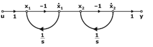
The state transition matrix eAt of the system shown in figure above is:
(GATE 2013 || EC || MCQ||2 MARK)
[Tex]\begin{bmatrix} e^{-t} & 0 \\ te^{-t} & e^{-t} \end{bmatrix}[/Tex]
[Tex]\begin{bmatrix} e^{-t} & 0 \\ -te^{-t} & e^{-t} \end{bmatrix}[/Tex]
[Tex]\begin{bmatrix} e^{-t} & 0 \\ e^{-t} & e^{-t} \end{bmatrix}[/Tex]
[Tex]\begin{bmatrix} e^{-t} & -te^{-t} \\ 0 & e^{-t} \end{bmatrix}[/Tex]
Question 2
Consider a system S represented in state space as
[Tex]\frac{dx}{dt} = \begin{bmatrix} 0 & -2 \\ 1 & -3 \end{bmatrix} x + \begin{bmatrix} 1 \\ 0 \end{bmatrix} r[/Tex]
Which of the state space representations given below has/have the same transfer function as that of S ?
( GATE 2024 || EC || MSQ||2 MARK)
[Tex]\frac{dx}{dt} = \begin{bmatrix} 0 & 1 \\ -2 & -3 \end{bmatrix} x + \begin{bmatrix} 1 \\ 0 \end{bmatrix} r, y = \begin{bmatrix} 1 & 2 \end{bmatrix} x[/Tex]
[Tex]\frac{dx}{dt} = \begin{bmatrix} 0 & 1 \\ -2 & -3 \end{bmatrix} x + \begin{bmatrix} 1 \\ 0 \end{bmatrix} r, y = \begin{bmatrix} 0 & 2 \end{bmatrix} x[/Tex]
[Tex]\frac{dx}{dt} = \begin{bmatrix} -1 & 0 \\ 0 & -2 \end{bmatrix} x + \begin{bmatrix} -1 \\ 3 \end{bmatrix} r, y = \begin{bmatrix} 1 & 1 \end{bmatrix} x[/Tex]
[Tex]\frac{dx}{dt} = \begin{bmatrix} -1 & 0 \\ 0 & -2 \end{bmatrix} x + \begin{bmatrix} 1 \\ 1 \end{bmatrix} r, y = \begin{bmatrix} 1 & 2 \end{bmatrix} x[/Tex]
Question 3
Consider a system where x1(t),x2(t)x1(t),x2(t), and x3(t)x3(t) are three internal state signals and u(t)u(t) is the input signal. The differential equations governing the system are given by
[Tex]\frac{d}{dt} \begin{bmatrix} x_1(t) \\ x_2(t) \\ x_3(t) \end{bmatrix} = \begin{bmatrix} 2 & 0 & 0 \\ 0 & -2 & 0 \\ 0 & 0 & 0 \end{bmatrix} \begin{bmatrix} x_1(t) \\ x_2(t) \\ x_3(t) \end{bmatrix} + \begin{bmatrix} 1 \\ 1 \\ 1 \end{bmatrix} u(t)[/Tex]
Which of the following statements is/are TRUE?
(GATE 2025 || EC || MCQ||2 MARK)
The signals x1(t),x2(t)x1(t),x2(t), and x3(t)x3(t) are bounded for all bounded inputs
There exists a bounded input such that at least one of the signals x1(t),x2(t)x1(t),x2(t), and x3(t)x3(t) is unbounded
There exists a bounded input such that the signals x1(t),x2(t)x1(t),x2(t), and x3(t)x3(t) are unbounded
The signals x1(t),x2(t)x1(t),x2(t), and x3(t)x3(t) are unbounded for all bounded inputs
Question 4
A network is described by the state model as
X1 = 2x1 – x2 + 3u,
X2 = – 4x2 – u,
Y = 3x1 – 2x2
The transfer function H(s) = [Tex]\left( \frac{Y(s)}{U(s)} \right)[/Tex]
is:
(GATE 2015 || EC || MCQ||2 MARK)
[Tex]\frac{11s + 35}{(s - 2)(s + 4)}[/Tex]
[Tex]\frac{11s + 38}{(s - 2)(s + 4)}[/Tex]
[Tex]\frac{11s - 35}{(s - 2)(s + 4)}[/Tex]
[Tex]\frac{11s - 38}{(s - 2)(s + 4)}[/Tex]
Question 5
A second-order linear time-invariant system is described by the following state equations
[Tex]\frac{d}{dt}[/Tex]
x1 (t)+ 2x1 (t) = 3u(t),
[Tex]\frac{d}{dt}[/Tex]
x1 (t)+ x2(t) = u(t);
where x1(t) and x2(t) are the two state variables and u(t) denotes the input if the output c(t) = x1(t), then the system is
( GATE 2016 || EC || MCQ||2 MARK)
controllable but not observable.
observable but not controllable.
both controllable and observable.
neither controllable nor observable.
Question 6
Consider the state space realization:
[Tex]\begin{bmatrix} x'_1(t) \\ x'_2(t) \end{bmatrix} = \begin{bmatrix} 0 & 0 \\ 0 & -9 \end{bmatrix} \begin{bmatrix} x_1(t) \\ x_2(t) \end{bmatrix} + \begin{bmatrix} 0 \\ 45 \end{bmatrix} u(t),[/Tex]
with the initial condition
[Tex]\begin{bmatrix} x_1(0) \\ x_2(0) \end{bmatrix} = \begin{bmatrix} 0 \\ 0 \end{bmatrix};[/Tex]
where u(t) denotes the unit step function the value of
[Tex]\lim_{x \to \infty} |\sqrt{x_1^2(t) + x_2^2(t)} [/Tex] is
____________
( GATE 2017 || EC || NAT||2 MARK)
5.0
Question 7
A second-order LTI system is described by the following state equations:
[Tex]\frac{d}{dt} x_1(t) - x_2(t) = 0[/Tex]
[Tex]\frac{d}{dt} x_2(t) + 2x_1(t) + 3x_2(t) = r(t);[/Tex]
Where x1(t) and x2(t) are two state variables and r(t) denotes the input. The input c(t) = x1(t).
The system is
( GATE 2017 || EC || MCQ||2 MARK)
Undamped (oscillatory)
Underdamped
Critically damped
Overdamped
Question 8
The state equation and the output equation of a control system are given below:
[Tex]\mathbf{x} = \begin{bmatrix} -4 & -1.5 \\ 4 & 0 \end{bmatrix} \mathbf{x} + \begin{bmatrix} 2 \\ 0 \end{bmatrix} u[/Tex]
[Tex]Y = \begin{bmatrix} 1.5 & 0.625 \end{bmatrix} \mathbf{x}[/Tex]
The transfer function representation of the system is:
( GATE 2018 || EC || MCQ||2 MARK)
[Tex]\frac{3s + 5}{s^2 + 4s + 6}[/Tex]
[Tex]\frac{3s + 1.875}{s^2 + 4s + 6}[/Tex]
[Tex]\frac{4s + 1.5}{s^2 + 4s + 6}[/Tex]
[Tex]\frac{6s + 5}{s^2 + 4s + 6}[/Tex]
Question 9
Let the state-space representation of an LT1 system be x’(t) = Ax (t) + Bu(t),
y(t) = Cx(t) + du (t) where A, B, C are matrices, d is a scalar, u(t) is the input to the system, and y (t) is its output. Let B = [0 0 1]T and d = 0. Which one of the following options for A and C will ensure that the transfer function of this LTI system is?
[Tex]H(s) = \frac{1}{s^3 + 3s^2 + 2s + 1}?[/Tex]
(GATE 2019 || EC || MCQ||2 MARK)
[Tex]A = \begin{bmatrix} 0 & 1 & 0 \\ 0 & 0 & 1 \\ -1 & -2 & -3 \end{bmatrix} \text{ and } C = \begin{bmatrix} 1 & 0 & 0 \end{bmatrix}[/Tex]
[Tex]A = \begin{bmatrix} 0 & 1 & 0 \\ 0 & 0 & 1 \\ -2 & -2 & -3 \end{bmatrix} \text{ and } C = \begin{bmatrix} 0 & 0 & 1 \end{bmatrix}[/Tex]
[Tex]A = \begin{bmatrix} 0 & 1 & 0 \\ 0 & 0 & 1 \\ -3 & -2 & -1 \end{bmatrix} \text{ and } C = \begin{bmatrix} 0 & 0 & 1 \end{bmatrix}[/Tex]
[Tex]A = \begin{bmatrix} 0 & 1 & 0 \\ 0 & 0 & 1 \\ -3 & -2 & -1 \end{bmatrix} \text{ and } C = \begin{bmatrix} 1 & 0 & 0 \end{bmatrix}[/Tex]
Question 10
The electrical system shown in the figure converts input source current iS(t) to output voltage vo(t)
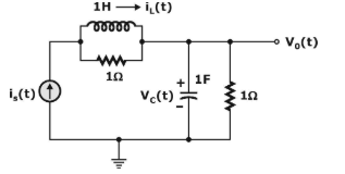
Current iL(t) in the inductor and voltage vc(t) across the capacitor is taken as the state variables, both assumed to be initially equal to zero, i.e., iL(0) = 0 and v0(0) = 0 The system is
( GATE 2021 || EC || MCQ||2 MARK)
neither state controllable nor observable
completely state controllable but not observable
completely observable but not state controllable
completely state controllable as well as completely observable
There are 31 questions to complete.