- Courses
- Tutorials
- Interview Prep
GATE EC || DIGITAL LOGIC || ADC & DAC || PYQS (2000-2025)
Question 1
A 10-bit D/A converter is calibrated over full range from 0 to 10V. If the input to the D/A converter is 13A (in hexadecimal number). Then output voltage is?
(GATE 2020 || EC || MCQ || 1 MARK)
3.050 t0 3.080
Question 2
A full-scale sinusoidal signal is applied to a 10-bit ADC. The fundamental component of the ADC output has a normalized power of 1 W, and the total noise and distortion power is 10 µW. The effective number of bits (rounded off to the nearest integer) of the ADC is
(GATE 2024 || EC || MCQ || 2 MARK)
7
8
9
10
Question 3
Consider the circuit shown with an ideal Op-Amp. The output voltage V0 is ? (rounded off to two decimal places).
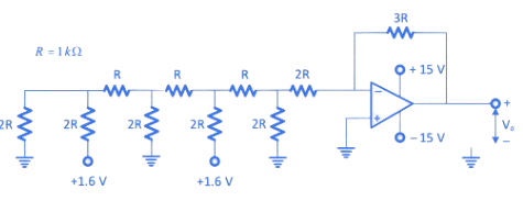
(GATE 2022 || EC || NAT || 2 MARK)
-0.75
Question 4
A 10-bit analog-to-digital converter (ADC) has a sampling frequency of 1 MHz and a full scale voltage of 3.3 V . For an input sinusoidal signal with frequency 500 kHz , the maximum SNR (in dB, rounded off to two decimal places) and the data rate (in Mbps) at the output of the ADC are ?
( GATE 2025 || EC || MCQ || 1 MARK)
61.96 and 10
61.96 and 5
33.36 and 10
33.6 and 5
Question 5
The signal-to-noise ratio (SNR) of an ADC with a full-scale sinusoidal input is 61.96 dB. The resolution of the ADC, rounded to the nearest integer, is ______ bits.
(GATE 2023 || EC || MCQ || 1 MARK)
10
Question 6
A 4-bit weighted-resistor DAC with inputs b₃, b₂, b₁, and b₀ (from MSB to LSB) is designed using an ideal op-amp, as shown below. The switches are closed when the corresponding input bits are logic '1' and open otherwise. When the input b₃ b₂ b₁ b₀ changes from 1110 to 1101, the magnitude of the change in the output voltage V₀ (in mV, rounded to the nearest integer) is
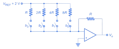
(GATE 2025 || EC || MCQ || 1 MARK)
250
Question 7
In the following circuit, the comparator output is logic "1" if V1 > V2 and logic "0" otherwise. The D/A conversion is done as per the relation:
VDAC = Σ(2(n−1) bn) Volts
where b3 (MSB), b2, b1, and b0 (LSB) are the counter outputs. The counter starts from the clear state.
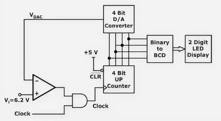
The stable reading of the LED display is
(GATE 2008 || EC || MCQ || 1 MARK)
6
7
12
13
Question 8
In the digital-to-analog converter (DAC) circuit shown in the figure, the reference voltage VR = 10 V and R = 10 kΩ. Determine the output voltage Vo

(GATE 2007 || EC || MCQ || 2 MARK)
-0.781 V
-1.562 V
-3.125 V
-6.250 V
Question 9
In the digital-to-analog converter (DAC) circuit shown in the figure, the reference voltage VR = 10 V and R = 10 kΩ. Determine the current i flowing through the rightmost 2R branch.
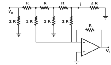
(GATE 2007 || EC || MCQ || 2 MARK)
31.25μA
62.5μA
125μA
. 125μA
Question 10
Consider a four-bit D to A converter. The analog value corresponding to a digital signal of values 0000 and 0001 are 0 V and 0.0625 V, respectively. The analog value (in Volts) corresponding to the digital signal 1111 is
(GATE 2015 || EC || MCQ || 1 MARK)
(0.93 to 0.94)
There are 21 questions to complete.