- Courses
- Tutorials
- Interview Prep
GATE EC||ANALOG ELECTRONIC||DIODE||PYQS(2000-2025)
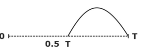
Question 1
For the circuit with ideal diodes shown in the figure, the shape of the output (Vout) for the given sine wave input (Vin) will be
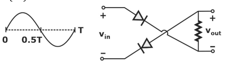
( GATE 2015 || EC || PYQ || MCQ ||1 MARK)
Question 2
An asymmetrical periodic pulse train Vin of 10 V amplitude with on-time TON = 1 ms and off-time TOFF =1 μs is applied to the circuit shown in the figure. The diode D1 is ideal.
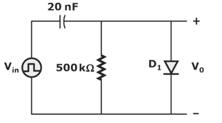
The difference between the maximum voltage and minimum voltage of the output waveform Vo (in integer) is ____V.
( GATE 2021 || EC || PYQ || NAT ||2 MARK)
10
Question 3
In the circuit shown below all component ideal, input voltage is sinusoidal.
Magnitude of steady state output Vo is ___________ V.
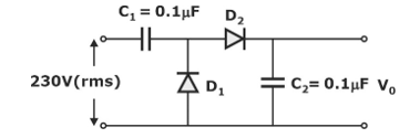
(GATE 2020 || EC || PYQ || NAT ||1 MARK)
650.5
Question 4
In the circuit shown, Vs is a 10 V square wave of period, T = 4 ms with R = 500 Ω and C = 10 μF. The capacitor is initially unchanged at t = 0, and the diode is assumed to be ideal. The voltage across the capacitor (VC) at 3 ms is equal to …….. volts (rounded off to one decimal place).
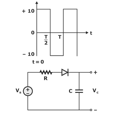
(GATE 2019 || EC || PYQ || NAT ||2 MARK)
3.31
Question 5
In the circuit shown, Vs is a square wave of period T with maximum and minimum values of 8V and -10V, respectively. Assume that the diode is ideal and
R1 = R2 = 50 Ω. The average value of VL is ……… volts (rounded off to 1 decimal place).

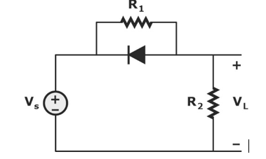
(GATE 2019 || EC || PYQ || NAT || 1 MARK)
-3
Question 6
A DC current of 26 μA flows through the circuit shown. The diode in the circuit is forward biased and it has an ideality factor of one. At the quiescent point, the diode has a junction capacitance of 0.5 nF. Its neutral region resistances can be neglected. Assume that the room temperature thermal equivalent voltage is 26 mV.
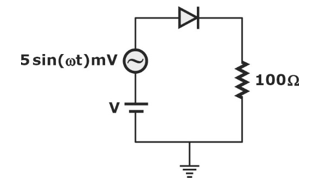
For ω = 2 × 10⁶ rad/s, the amplitude of the small-signal component of diode current (in μA) correct to one decimal place is ……………
(GATE 2018 || EC || PYQ || NAT || 2 MARK)
6.4
Question 7
The output V0 of the diode circuit shown in the figure is connected to an averaging DC voltmeter. The reading on the DC voltmeter in Volts, neglecting the voltage drop across the diode, is ………….
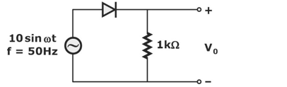
(GATE 2017 || EC || PYQ || NAT || 1 MARK)
3.183
Question 8
The diodes D1 and D2 in the figure are ideal and the capacitors are identical. The product RC is very large compared to the time period of the ac voltage. Assuming that the diodes do not breakdown in the reverse bias, the output voltage V0 (in volt) at the steady state is……………….

(GATE 2016 || EC ||PYQ || NAT ||1 MARK)
0
Question 9
The figure shows a half-wave rectifier with a 475 μF filter capacitor. The load draws a constant current I0 = 1 A from the rectifier. The figure also shows the input voltage Vi the output voltage Vc and the peak-to-peak voltage ripple u on Vc. The input voltage Vi is a triangle-wave with an amplitude of 10 V and a period of 1 ms.
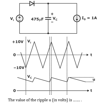
(GATE 2016 || EC || PYQ || NAT ||2 MARK)
2.105
Question 10
Assume that the diode in the figures has Von = 0.7 V, but is otherwise ideal.
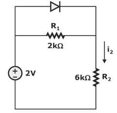
The magnitude of the current i2 (in mA) is equal to ………
(GATE 2016 || EC || PYQ || NAT ||1 MARK)
0.25
There are 28 questions to complete.