- Courses
- Tutorials
- Interview Prep
GATE EC||ANALOG ELECTRONIC||OPERATIONAL AMPLIFIER||PYQS(2000-2025)
Question 1
An ideal op-amp is an ideal
(GATE 2004|| EC || MCQ || 1 MARKS)
voltage controlled current source.
voltage controlled voltage source.
current controlled current source.
current controlled voltage source.
Question 2
If Vi = V1 sin (ωt) and V0 = V2 sin (ωt + ϕ), then the minimum and maximum values of ϕ (in radians) are respectively
(GATE 2007|| EC || MCQ || 2 MARK)
[Tex]-\frac{\pi}{2} \quad \text{and} \quad \frac{\pi}{2}[/Tex]
[Tex]0 \quad \text{and} \quad \frac{\pi}{2}[/Tex]
[Tex]-\pi \quad \text{and} \quad 0[/Tex]
[Tex]-\frac{\pi}{2} \quad \text{and} \quad 0[/Tex]
Question 3
Consider the Op-Amp circuit shown in the figure.
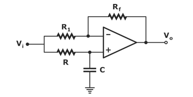
The transfer function V0(s)/Vi(s) is
(GATE 2007|| EC || MCQ || 2 MARK)
[Tex]\frac{1 - sRC}{1 + sRC}[/Tex]
[Tex]\frac{1 + sRC}{1 - sRC}[/Tex]
[Tex]\frac{1}{1 - sRC}[/Tex]
[Tex]\frac{1}{1 + sRC}[/Tex]
Question 4

[Tex]V_{o2} = \sqrt{2}\,V_{o1}[/Tex]
[Tex]V_{o2} = e^2 V_{01}[/Tex]
[Tex]V_{o2} = V_{o1}\ln 2[/Tex]
[Tex]V_{o1} - V_{o2} = V_T \ln 2[/Tex]
Question 5
For the Op-Amp circuit shown in the figure, V0 is
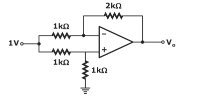
(GATE 2007 || EC || MCQ || 2 MARK)
2 V
-1 V
-0.5 V
0.5 V
Question 6
For the circuit shown in the following figure, the capacitor C is initially uncharged. At t = 0, the switch S is closed. The voltage Vc across the capacitor at t = 1 millisecond is
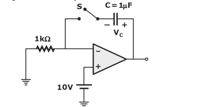
For the circuit shown in the following figure, the capacitor C is initially uncharged. At t = 0, the switch S is closed. The voltage Vc across the capacitor at t = 1 millisecond is
(GATE 2006 || EC || MCQ || 2 MARK)
0 Volt
6.3 Volts
9.45Volts
10 Volts
Question 7
The voltage e0 indicated in the figure has been measured by an ideal voltmeter. Which of the following can be calculated?
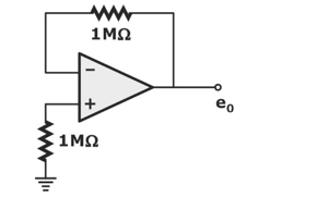
(GATE 2005|| EC || MCQ || 2 MARK)
Bias current of the inverting input only.
Bias current of the inverting and non-inverting inputs only.
Input offset current only
Both the bias currents and the input offset current
Question 8
The input resistance Ri of the amplifier shown in the figure is
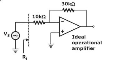
(GATE 2005|| EC || MCQ || 1 MARK)
30/4 kΩ
10 kΩ
40 k Ω
infinite
Question 9
In the op-amp circuit given in the figure, the load current iL is
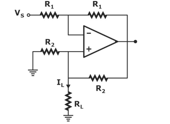
(GATE 2004|| EC || MCQ || 1 MARKS)
[Tex]-\frac{V_s}{R_2}[/Tex]
[Tex]\frac{V_s}{R_2}[/Tex]
[Tex]\frac{V_s}{R_L}[/Tex]
[Tex]-\frac{V_s}{R_1}[/Tex]
Question 10
The circuit in the figure is
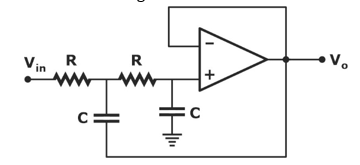
(GATE 2004|| EC || MCQ || 1 MARKS)
low-pass filter
high-pass filter
band-pass filter
band-reject filter
There are 20 questions to complete.