- Courses
- Tutorials
- Interview Prep
GATE EC||NETWORK THEORY||TRANSIENT ANALYSIS||PYQS(2000-2025)
Question 1
In following figure, C1 and C2 are ideal capacitors. C1 had been charged to 12V before the ideal switch S is closed at t = 0. The current i(t) for all t is
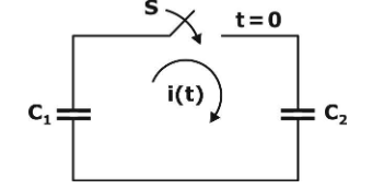
(MCQ || 2012 || MCQ || 1 mark)
zero
a step function
an exponentially decaying function
an impulse function
Question 2
In the figure, the switch was closed for a long time before opening at t = 0. The voltage Vx at t = 0+ is
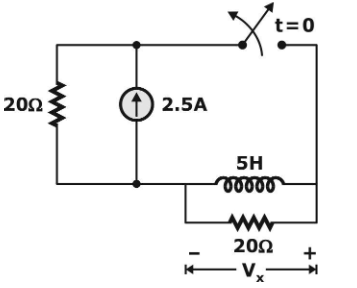
(MCQ || 2002 || MCQ || 1 mark)
25 V
50 V
–50 V
0 V
Question 3
At t = 0+, the current i1 is
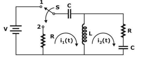
(MCQ || 2003 || MCQ || 2 mark)
-V/ 2R
-V/ R
-V/ 4R
zero
Question 4
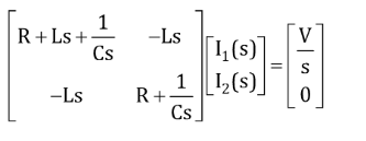
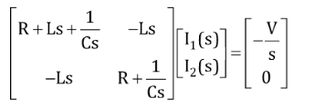
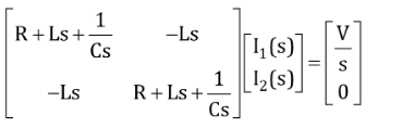
I1(s) and I2(s) are the Laplace transforms of i1(t) and i2(t), respectively. The equations for the loop currents I1(s) and I2(s) for the circuit shown in the figure (in question 25) after the switch is brought from position 1 to position 2 at t = 0 are
(MCQ || 2003 || MCQ || 2 mark)

Question 5
(MCQ || 2004 || MCQ || 2 mark)
Question 6
![]()
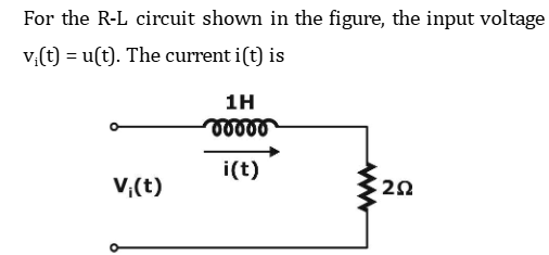
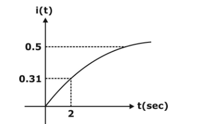
At t = 2 s,
![]()
(MCQ || 2006 || MCQ || 1 mark)
0.5 A
2.0 A
1.0 A
0.0 A
Question 7
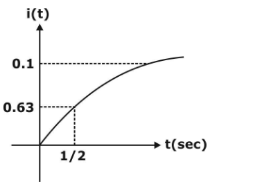
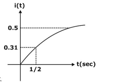
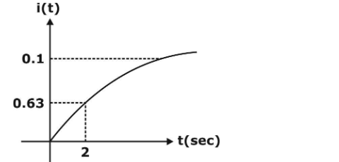
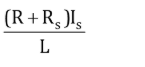
In the circuit shown, VC is 0 volts at t = 0 sec. For t > 0, the capacitor current ic(t), where t is in seconds, is given by
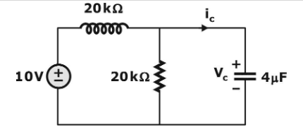
(MCQ || 2007 || MCQ || 2 mark)
0.50 exp (–25t) mA
0.25 exp (–25t) mA
0.50 exp (–12.5t) mA
0.25 exp (–6.25t) mA
Question 8
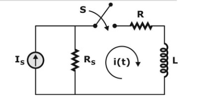
In the following circuit, the switch S is closed at t = 0. The rate of change of current ![]() is given by
is given by
(MCQ || 2008 || MCQ || 2 mark)
0

.
.

Question 9
In the circuit shown below, the initial charge on the capacitor is 2.5 mC, with the voltage polarity as indicated. The switch is closed at time t = 0. The current i(t) at a time t after the switch is closed is
(MCQ || 2011 || MCQ || 1 mark)
i(t) = 15 exp (–2×10³t) A
i(t) = 5 exp (–2×10³t) A
i(t) = 10 exp (–2×10³t) A
i(t) = –5 exp (–2×10³t) A
Question 10
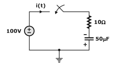
The current in the RL-circuit shown below is i(t) = 10 cos (5t – /4)A
The value of the inductor (rounded off to two decimal places) is ……. H.
(NAT || 2020 || MCQ || 1 mark)
2.828
There are 34 questions to complete.