ESP32-P4-EYE
This user guide will help you get started with ESP32-P4-EYE and will also provide more in-depth information.
ESP32-P4-EYE is a vision development board based on the ESP32-P4 chip, mainly targeting camera applications. ESP32-P4 features a dual-core 400 MHz RISC-V processor and supports up to 32 MB of PSRAM. In addition, ESP32-P4 supports USB 2.0 standard, MIPI-CSI/DSI, H264 Encoder, and various other peripherals. With all of its outstanding features, the board is an ideal choice for developing low-cost, high-performance, low-power network-connected audio and video products.
The board integrates the ESP32-C6-MINI-1U module for Wi-Fi and Bluetooth communication. It supports MIPI-CSI camera interface and USB 2.0 High-Speed device mode. Rich onboard features include a camera, display, microphone, and MicroSD card, enabling real-time monitoring of the environment and collection of image and audio data. It is suitable for applications such as smart surveillance cameras, vision model detection, and edge computing in IoT that require real-time image processing and wireless communication.
Most of the I/O pins are broken out to the pin header for easy interfacing. Developers can connect peripherals with jumper wires.

ESP32-P4-EYE Front View (click to enlarge)

ESP32-P4-EYE Back View (click to enlarge)
This guide includes the following sections:
Getting Started: Overview of ESP32-P4-EYE and hardware/software setup instructions to get started.
Hardware Reference: More detailed information about the ESP32-P4-EYE’s hardware.
Hardware Revision Details: Revision history, known issues, and links to user guides for previous versions (if any) of ESP32-P4-EYE.
Related Documents: Links to related documentation.
Getting Started
This section provides a brief introduction to ESP32-P4-EYE, instructions on how to do the initial hardware setup and how to flash firmware onto it.
Description of Components

ESP32-P4-EYE PCB Top View (click to enlarge)

ESP32-P4-EYE Front View (click to enlarge)
The key components of the top PCB are described in a clockwise direction. To facilitate use, these components or interfaces are also marked on the ESP32-P4-EYE enclosure.
Key Component |
Description |
|---|---|
MicroSD Card Slot |
Supports a MicroSD card in 4-line SDIO and SPI modes. |
Test Points |
Provides access points for programming and testing the ESP32-C6-MINI-1U; can be connected via Dupont wires. |
USB 2.0 Device Port |
Connected to the USB 2.0 OTG High-Speed interface of ESP32-P4, compliant with the USB 2.0 specification. When communicating with other devices via this port, ESP32-P4 acts as a USB device connecting to a USB host. USB 2.0 Device Port can also be used for powering the board. Marked with |
USB Debug Port |
Used for board power, firmware flashing, and connecting to USB-Serial-JTAG interface of ESP32-P4. Marked with |
Power Switch |
Flip to “I” to power on the board with 5 V input; flip to “O” to power off. |
User-defined Buttons |
Customizable by user application. |
LCD FPC Connector |
Connects to a 1.54-inch LCD screen. |
LCD |
1.54-inch LCD with 240 × 240 resolution and SPI interface, capable of displaying real-time images from the camera. For details, refer to Display Datasheet. |
Charging Indicator |
When the battery is charging, the indicator light is red; once charging is complete, the light turns green. |

ESP32-P4-EYE PCB Bottom View (click to enlarge)
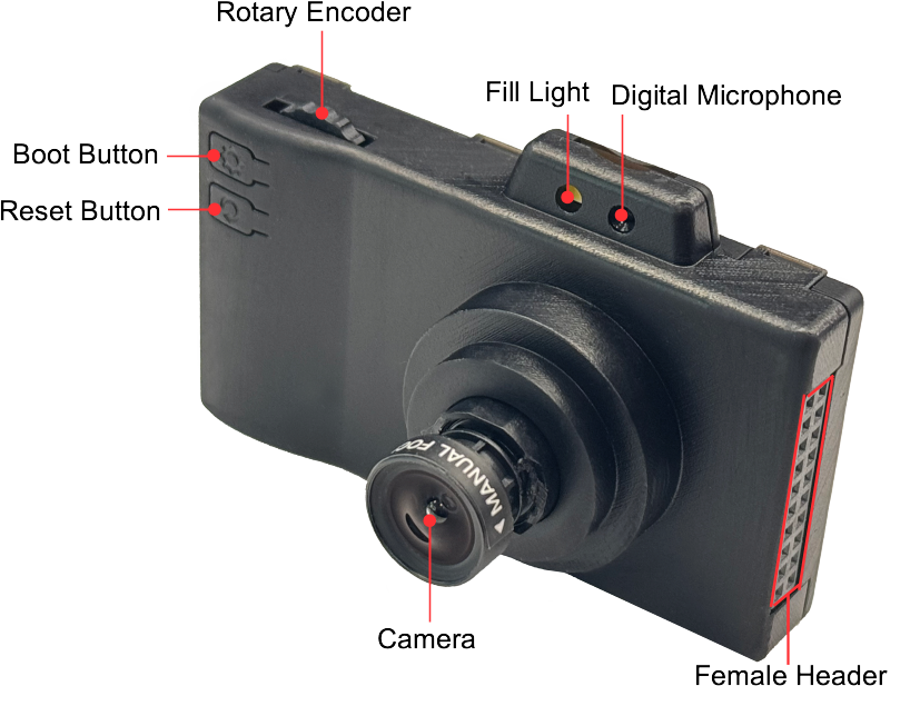
ESP32-P4-EYE Back View (click to enlarge)
The key components of the back PCB are described in a clockwise direction. To facilitate use, these components or interfaces are also marked on the ESP32-P4-EYE enclosure.
Key Component |
Description |
|---|---|
Rotary Encoder |
You can customize functions based on your application, such as using it to control LCD interface or adjust camera zoom levels. |
ESP32-C6-MINI-1U |
Serves as the Wi-Fi and Bluetooth communication module. |
Fill Light |
Provides illumination for image capture and video recording. |
Digital Microphone |
Used for voice recognition or audio recording. |
MIPI CSI Connector |
Connects to the camera module. |
Female Header |
2 x 10P header, customizable based on application. |
SPI flash |
16 MB flash connected via the SPI interface. |
ESP32-P4 |
High-performance MCU with large internal memory; supports advanced image and voice processing. |
Battery Connector |
Connects to a lithium battery. |
Reset Button |
Resets the board. Marked with |
Boot Button |
Controls boot mode. Marked with |
Camera |
2 MP resolution with manually adjustable focal length. For details, refer to Camera Datasheet. |
Application Development
Before powering up your ESP32-P4-EYE, please make sure that it is in good condition with no obvious signs of damage.
Required Hardware
ESP32-P4-EYE
USB cables
Computer running Windows, Linux, or macOS
Note
Be sure to use a good quality USB cable. Some cables are for charging only and do not provide the needed data lines nor work for programming the boards.
Optional Hardware
MicroSD card
Lithium battery
Hardware Setup
Connect ESP32-P4-EYE to your computer using a USB cable. The board can be powered through the USB 2.0 Device Port or USB Debug Port. The USB Debug Port is recommended for flashing firmware and debugging.
Software Setup
To set up your development environment and flash an application example onto your board, please follow the installation instructions in ESP-IDF Get Started.
You can find examples for ESP32-P4-EYE by accessing Examples . To configure project options, enter idf.py menuconfig in the example directory.
Hardware Reference
Functional Block Diagram
The block diagram below shows the components of ESP32-P4-EYE and their interconnections.

ESP32-P4-EYE Functional Block Diagram (click to enlarge)
Power Supply Options
ESP32-P4-EYE can be powered using the following methods:
Via the
USB 2.0 Device PortorUSB Debug Port
Connect ESP32-P4-EYE to a power source using a USB Type-C cable through either of the two ports. If a lithium battery is already installed, it will be charged simultaneously.
Via the
Battery Connector
To use this method, first open the enclosure, then connect the battery to the Battery Connector. The lithium battery must not exceed 4 mm × 25 mm × 45 mm in size. It should use a 1.25 mm pitch connector, and the polarity must match the markings on the PCB.

Battery Connection (click to enlarge)
Female Header

Female Header (Click to Enlarge)
USB 2.0 Device Port Circuit
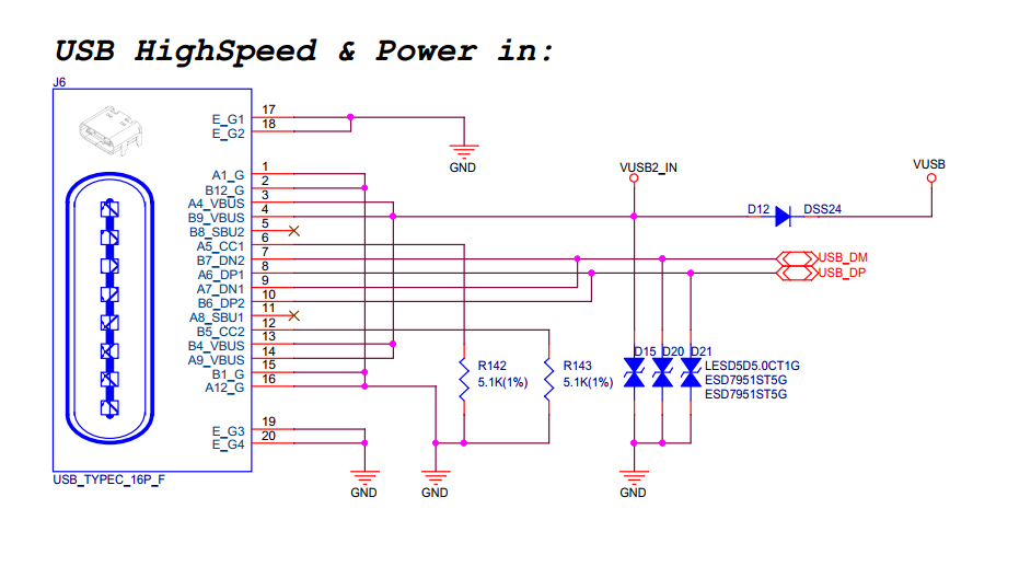
USB 2.0 Device Port Circuit (Click to Enlarge)
LCD Circuit

LCD Circuit (Click to Enlarge)
Please note that this interface supports SPI displays. ESP32-P4-EYE features the ST7789, which uses the LCD_BL pin (GPIO20) to control the backlight.
MicroSD Card Slot Interface Circuit

MicroSD Card Slot Interface Circuit (Click to Enlarge)
Please note that the MicroSD card interface supports 1-bit and 4-bit SDIO modes, as well as SPI mode.
Charging Circuit

Charging Circuit (Click to Enlarge)
Microphone Circuit
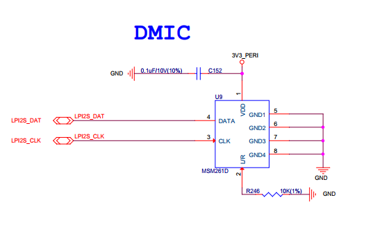
Microphone Circuit (Click to Enlarge)
Camera Circuit

Camera Circuit (Click to Enlarge)
Rotary Encoder Circuit

Rotary Encoder Circuit (Click to Enlarge)
ESP32-C6-MINI-1U Module Circuit

ESP32-C6-MINI-1U Module Circuit (Click to Enlarge)
Hardware Revision Details
No previous versions available.