Register Transfer Language (RTL)
Last Updated :
10 Oct, 2025
Register Transfer Language (RTL) is a design abstraction used to describe the behavior and structure of digital circuits, specifically focusing on the transfer of data between registers and the operations performed on that data—such as addition, subtraction, shifting, and logical operations.
- It defines how data moves from one register to another and how it is processed within a digital system.
- RTL enables a high-level representation of circuit behavior, linking algorithmic design with low-level hardware implementation for purposes such as simulation, synthesis, and verification.
- It is primarily applied to the representation of synchronous circuits, which are controlled by clock signals.
- RTL designs are typically captured using hardware description languages (HDLs) such as Verilog or VHDL.
- It is widely used in the design of Application Specific Integrated Circuits (ASICs), Field Programmable Gate Arrays (FPGAs), and other custom digital hardware.
Usage of RTL in Digital Design
Register Transfer Language (RTL) describes the flow of data within a digital system by detailing the micro-operations performed on data stored in registers. Here are some uses of RTL design.

Micro-operations: The operations executed on the data store in registers are called micro-operations. They are detailed low-level instructions used in some designs to implement complex machine instructions.
Register Transfer: The information transferred from one register to another register is represented in symbolic form by the replacement operator and is called Register Transfer.
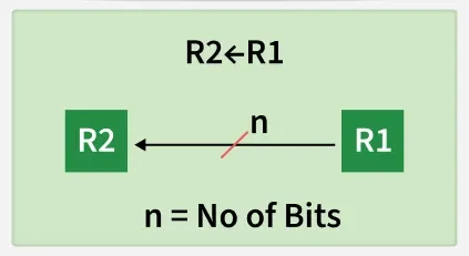
Replacement Operator: In the statement, R2 <- R1, <- acts as a replacement operator. This statement defines the transfer of the content of register R1 into register R2.
Register Representation: There are various methods of RTL:
- The general way of representing a register is by the name of the register enclosed in a rectangular box, as shown in (a).
- Numbered sequentially from 0 to (n-1).
- With bit numbering marked along the top of the box.
- Divided into sections, like a 16-bit register (PC) split into lower and higher bytes (bits 0-7 and 8-15, respectively).
Register Transfer Operations
The operation performed on the data stored in the registers are referred to as register transfer operations.
There are different types of register transfer operations:
Simple Transfer
The content of R1 are copied into R2 without affecting the content of R1. It is an unconditional type of transfer operation.
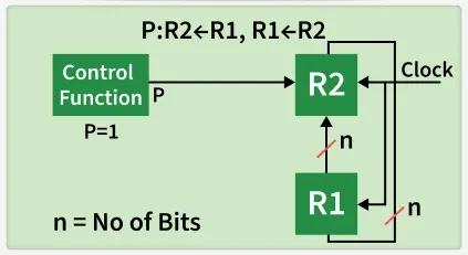
Conditional Transfer
It indicates that if P=1, then the content of R1 is transferred to R2. It is a unidirectional operation.

Simultaneous Operations
If 2 or more operations are to occur simultaneously then they are separated with comma (,). If the control function P=1, then load the content of R1 into R2 and at the same clock load the content of R2 into R1.
Basic symbols of RTL
| Symbol | Description | Example |
|---|
| Letters and Numbers | Denotes a Register | MAR, R1, R2 |
| ( ) | Denotes a part of register | R1(8-bit) R1(0-7) |
| <- | Denotes a transfer of information | R2 <- R1 |
| , | Specify two micro-operations of Register Transfer | R1 <- R2 R2 <- R1 |
| : | Denotes conditional operations | P : R2 <- R1 if P=1 |
| Naming Operator (:=) | Denotes another name for an already existing register/alias | Ra := R1 |