Mapping from ER Model to Relational Model
Last Updated :
03 Nov, 2025
Converting an Entity-Relations, hip (ER) diagram to a Relational Model is a crucial step in database design. The ER model represents the conceptual structure of a database, while the Relational Model is a physical representation that can be directly implemented using a Relational Database Management System (RDBMS) like Oracle or MySQL.
Different Cases
Case 1: Binary Relationship with 1:1 cardinality with total participation of an entity
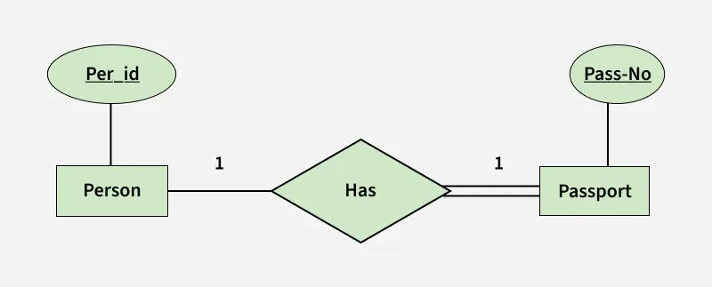 Binary Relationship with 1:1 cardinality with total participation of an entity
 Note: A person has 0 or 1 passport number and Passport is always owned by 1 person. So it is 1:1 cardinality with full participation constraint from Passport.
- First Convert each entity and relationship to tables.
- Person table corresponds to Person Entity with key as Per-Id. Similarly Passport table corresponds to Passport Entity with key as Pass-No.
- Has Table represents relationship between Person and Passport (Which person has which passport). So it will take attribute Per-Id from Person and Pass-No from Passport.
Table 1
| Person | | Has | | Passport |
| Per-Id | Other Person Attribute | Per-Id | Pass-No | Pass-No | Other PassportAttribute |
| PR1 | - | PR1 | PS1 | PS1 | - |
| PR2 | - | PR2 | PS2 | PS2 | - |
| PR3 | - | | | | | | |
- As we can see from Table 1, each Per-Id and Pass-No has only one entry in Has Table.
- So we can merge all three tables into 1 with attributes shown in Table 2. Each Per-Id will be unique and not null.
Table 2
| Per-Id | Other Person Attribute | Pass-No | Other PassportAttribute |
Note: So it will be the key. Pass-No can’t be key because for some person, it can be NULL.
Case 2: Binary Relationship with 1:1 cardinality and partial participation of both entities
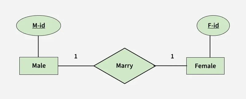 Binary Relationship with 1:1 cardinality and partial participation of both entities
 - A male marries 0 or 1 female and vice versa as well. So it is 1:1 cardinality with partial participation constraint from both.
- First Convert each entity and relationship to tables.
- Male table corresponds to Male Entity with key as M-Id. Similarly Female table corresponds to Female Entity with key as F-Id.
- Marry Table represents relationship between Male and Female (Which Male marries which female). So it will take attribute M-Id from Male and F-Id from Female.
Table 3
| Male | | Marry | | Female |
| M-Id | Other Male Attribute | M-Id | F-Id | F-Id | Other FemaleAttribute |
| M1 | - | M1 | F2 | F1 | - |
| M2 | - | M2 | F1 | F2 | - |
| M3 | - | | | | | F3 | - |
- As we can see from Table 3, some males and some females do not marry.
- If we merge 3 tables into 1, for some M-Id, F-Id will be NULL. So there is no attribute which is always not NULL.
- So we can’t merge all three tables into 1. We can convert into 2 tables. In table 4, M-Id who are married will have F-Id associated. For others, it will be NULL.
- Table 5 will have information of all females. Primary Keys have been underlined.
Table 4
| M-Id | Other Male Attribute | F-Id |
Table 5
| F-Id | Other FemaleAttribute |
Note: Binary relationship with 1:1 cardinality will have 2 table if partial participation of both entities in the relationship. If atleast 1 entity has total participation, number of tables required will be 1.
Case 3: Binary Relationship with n: 1 cardinality
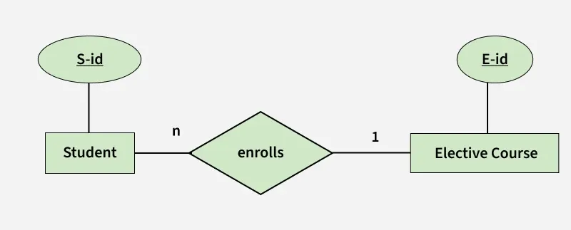 Binary Relationship with n: 1 cardinality
- In this scenario, every student can enroll only in one elective course but for an elective course there can be more than one student.
- First Convert each entity and relationship to tables. Student table corresponds to Student Entity with key as S-Id.
- Similarly Elective_Course table corresponds to Elective_Course Entity with key as E-Id.
- Enrolls Table represents relationship between Student and Elective_Course (Which student enrolls in which course). So it will take attribute S-Id from Student and E-Id from Elective_Course.
Table 6
| Student | | Enrolls | | Elective_Course |
| S-Id | Other Student Attribute | S-Id | E-Id | E-Id | Other Elective CourseAttribute |
| S1 | - | S1 | E1 | E1 | - |
| S2 | - | S2 | E2 | E2 | - |
| S3 | - | | S3 | E1 | | E3 | - |
| S4 | - | | S4 | E1 | | | |
- As we can see from Table 6, S-Id is not repeating in Enrolls Table. So it can be considered as a key of Enrolls table.
- Both Student and Enrolls Table’s key is same. We can merge it as a single table.
Table 7
| S-Id | Other Student Attribute | E-Id |
Table 8
| E-Id | Other Elective CourseAttribute |
Note: The resultant tables are shown in Table 7 and Table 8. Primary Keys have been underlined.
Case 4: Binary Relationship with m: n cardinality
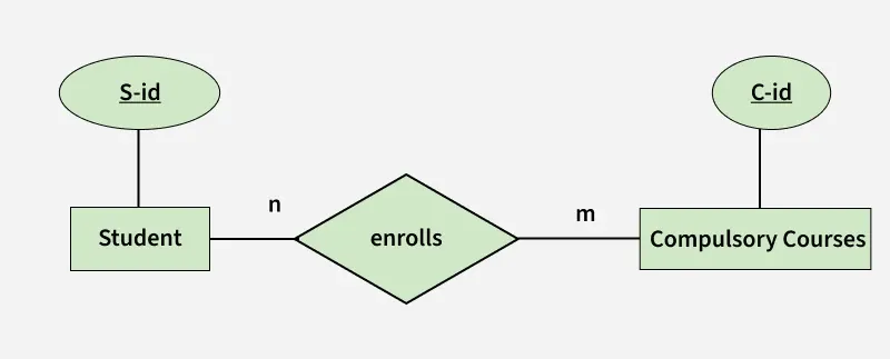 Binary Relationship with m: n cardinality
- In this scenario, every student can enroll in more than 1 compulsory course and for a compulsory course there can be more than 1 student.
- First Convert each entity and relationship to tables. Student table corresponds to Student Entity with key as S-Id.
- Similarly Compulsory_Courses table corresponds to Compulsory Courses Entity with key as C-Id.
- Enrolls Table represents relationship between Student and Compulsory_Courses (Which student enrolls in which course). So it will take attribute S-Id from Person and C-Id from Compulsory_Courses.
Table 9
| Student | | Enrolls | | Compulsory_Courses |
| S-Id | Other Student Attribute | S-Id | C-Id | C-Id | Other Compulsory CourseAttribute |
| S1 | - | S1 | C1 | C1 | - |
| S2 | - | S1 | C2 | C2 | - |
| S3 | - | | S3 | C1 | | C3 | - |
| S4 | - | | S4 | C3 | | C4 | - |
| | | | S4 | C2 | | | |
| | | | S3 | C3 | | | |
- As we can see from Table 9, S-Id and C-Id both are repeating in Enrolls Table.
- But its combination is unique; so it can be considered as a key of Enrolls table.
Note: All tables’ keys are different, these can’t be merged. Primary Keys of all tables have been underlined.
Case 5: Binary Relationship with weak entity
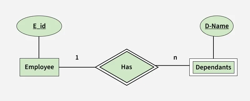 Binary Relationship with weak entity
- In this scenario, an employee can have many dependents and one dependent can depend on one employee.
- A dependent does not have any existence without an employee (e.g; you as a child can be dependent of your father in his company).
- So it will be a weak entity and its participation will always be total. Weak Entity does not have key of its own.
- So its key will be combination of key of its identifying entity (E-Id of Employee in this case) and its partial key (D-Name).
Table 10
| Employee | | Has | | Dependents |
| E-Id | Other Employee Attribute | E-Id | D-Name | D-Name | E-Id | Other DependentsAttribute |
| E1 | - | E1 | RAM | RAM | E1 | - |
| E2 | - | E1 | SRINI | SRINI | E1 | - |
| E3 | - | E2 | RAM | RAM | E2 | - |
| | | E3 | ASHISH | ASHISH | E3 | - |
- First Convert each entity and relationship to tables. Employee table corresponds to Employee Entity with key as E-Id.
- Similarly Dependents table corresponds to Dependent Entity with key as D-Name and E-Id.
- Has Table represents relationship between Employee and Dependents (Which employee has which dependents). So it will take attribute E-Id from Employee and D-Name from Dependents.
Table 11
| E-Id | Other Employee Attribute |
- As we can see from Table 10, E-Id, D-Name is key for Has as well as Dependents Table.
- So we can merge these two into 1.
Table 12
| D-Name | E-Id | Other DependentsAttribute |
Note: So the resultant tables are shown in Tables 11 and 12. Primary Keys of all tables have been underlined.
Conversion ER Model to Relational Model - Part1
Visit Course

Conversion ER Model to Relational Model - Part1
Conversion ER Model to Relational Model - Part2
Explore
Basics of DBMS
ER & Relational Model
Relational Algebra
Functional Dependencies & Normalisation
Transactions & Concurrency Control
Advanced DBMS
Practice Questions