Logic Gates - Definition, Types, Uses
Last Updated :
10 Apr, 2025
Logic Gates are the fundamental building blocks in digital electronics. There are basically seven main types of logic gates that are used to perform various logical operations in digital systems. By combining different logic gates, complex operations are performed, and circuits like flip-flops, counters, and processors are designed. In this article, we will see various types of logic gates in detail.
What is a Logic Gate?
A logic gates are an electronic circuit that are designed by using electrical components like diodes, transistors, resistors, and more. It is used to perform logical operations based on the inputs provided to it and gives a logical output that can be either high(1) or low(0). The operation of logic gates is based on Boolean algebra or mathematics. Logic gates find their uses in our day-to-day lives, such as in the architecture of our telephones, laptops, tablets and memory devices.
Types of Logic Gates
Logic gates can be broadly classified into three main categories :
AND GATE
An AND gate is used to perform logical Multiplication of binary input. The Output state of the AND gate will be high (1) if both the input is high (1), else the output state will be low(0) if any of the input is low (0).
The Boolean Expression or logic for the AND gate is the logical multiplication of inputs denoted by a full stop or single dot as :
A. B=X
The value of X will be True when both the inputs will be True.
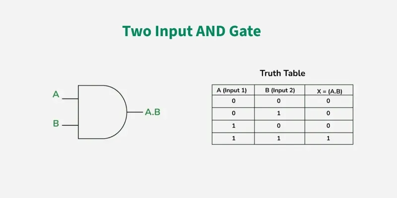 Two Input AND Gate
Properties of AND Gate
The following are two main properties of the AND gate:
- AND gate can accept two or more than two input values at a time.
- When all of the inputs are logic 1, the output of this gate is logic 1.
OR GATE
OR GATE is most widely used digital logic circuit. The output state of OR gate will be high i.e., (1) if any of the input state is high or 1, else output state will be low i.e., 0.
The Boolean Expression for the OR gate is the logical addition of inputs denoted by plus sign (+) as
X= A+B
The value of X will be high(true) when one of the inputs is set to high (true).
 Two Input OR Gate
Properties of OR Gate
An OR gate have the following two properties:
- It can have two or more input lines at a time.
- When all of the inputs to the OR gate are low or logic 0, the output of it is low or logic 0.
NOT GATE
In digital electronics, the NOT gate is one of the basic Logic Gate having only a single input and a single output. It is also known as inverter or inverting buffer. When the input signal is "low" the output signal is "high" and vice-versa.
The Boolean expression of NOT Gate is as follows
Y = Ā or
Y = A’
the value of Y will be high when A will be low.
 NOT Gate
Properties of NOT Gate
- The output of a NOT gate is complemented or inverse of the input applied to it.
- NOT gate takes only one output.
NOR GATE
The NOR gate is the type of universal logic gate. It takes two or more inputs and gives only one output. The output state of the NOR gate will be high (1) when all the inputs are low (0). NOR gate returns the complement result of the OR gate. It is basically a combination of two basic logic gates i.e., OR gate and NOT gate.
The Boolean expression of NOR gate is as follows:
If A and B are considered as two inputs, and O as output, then the expression for a two input NOR gate will be
O = (A + B)’
The value of O will be true when all of its inputs are set to 0.
 Two Input NOR Gate
Properties of NOR Gate
The following are two important properties of NOR gate:
- A NOR gate can have two or more inputs and gives an output.
- A NOR gate gives a high or logic 1 output only when it's all inputs are low or logic 0.
NAND GATE
The NAND Gate is another type of Universal logic gate. The NAND gate or "Not AND" is the combination of two basic logic gates AND gate and the NOT gate connected in series. It takes two or more inputs and gives only one output. The output of the NAND gate will give result high (1) when either of its input is high (1) or both of its input are low (0). In simple, it performs the inverted operation of AND gate.
The Boolean Expression of NAND Gate is as follows
Say we have two inputs, A and B and the output is called X, then the expression is
X = (A. B)’
 Two Input NAND Gate
Properties of NAND Gate
The following are the two key properties of NAND Gate
- NAND gate can take two or more inputs at a time and produces one output based on the combination of inputs applied.
- NAND gate produces a low or logic 0 output only when its all inputs are high or logic 1.
XOR GATE
In digital electronics, there is a specially designed logic gate named, XOR gate, which is used in digital circuits to perform modulo sum. It is also referred to as Exclusive OR gate or Ex-OR gate. it is used extensively in arithmetic logic circuits., logic comparators and error detection circuits. The XOR gate can take only two inputs at a time and give an output. The output of the XOR gate is high (1) only when its two inputs are dissimilar i.e., if one of them is low (0) then other one will be high (1).
Say we have two inputs, A and B and the output is called X, then the expression is
The Boolean expression of XOR Gate is as follows
X = A’B + AB’
 XOR Gate
 Properties of XOR Gate
The following two are the main properties of the XOR gate:
- It can accept only two inputs at a time. There is nothing like a three or more input XOR gate.
- The output of the XOR gate is logic 1 or high, when its inputs are dissimilar.
XNOR GATE
The XNOR is the combination of XOR gate and NOT gate. The output of the XNOR gate is high(1) when both the inputs are high (1) or low(0). In other words, the output of the XNOR gate is high(1) when both the inputs are the same. the XNOR gate can sometimes be called as Equivalence gate. In simple words, The XNOR gate is the complement of the XOR gate.
The following is the Boolean expression of the XNOR gate,
Y = A ⊙ B
Here, A and B are the input variables and Y is the output variable.
This expression can also be written as follows,
Y = AB + A’B’
We can also express the operation of an XNOR gate using XOR gate logic as follows:
Y = (A ⊕ B)’
 XNOR Gate
Properties of XNOR Gate
The following are two key properties of XNOR gate:
- XNOR gate takes only two inputs and produces one output.
- The output of the XNOR gate is high or logic 1 only when it has similar inputs.
Logic Gates in Programming
Design and Implementation of Adders in Digital Logic
Advanced Digital Logic
Applications of Logic Gates
Logic gates are the fundamental building blocks of all digital circuits and devices like computers. Here are some key digital devices in which logic gates are utilized to design their circuits.
Here are some devices, where logic gates is used;
Advantages of Logic Gates
Here are some advantages of logic gates over earlier technologies:
- Digital vs. Analog: Logic gates provide clear, stable binary operations (0 or 1), unlike noisy and less accurate analog systems.
- Precision and Accuracy: Logic gates offer higher precision and accuracy compared to analog systems, which were prone to signal variations.
- Simplified Circuit Design: Logic gates allow for simpler, more efficient circuit designs compared to earlier systems with many components (e.g., relays, switches).
- Speed and Efficiency: Logic gates enable faster, more efficient processing compared to older mechanical or vacuum tube-based systems.
- Smaller Size and Integration: Logic gates allow for miniaturized, compact devices through integrated circuits (ICs).
- Lower Power Consumption: Logic gates use less power and generate less heat compared to older technologies like vacuum tubes.
- Greater Reliability and Durability: Logic gates are more reliable and durable, with fewer parts prone to wear and tear than older systems.
- Ease of Troubleshooting: Digital circuits based on logic gates are easier to troubleshoot due to their predictable binary nature.
- Scalability and Flexibility: Logic gates are highly scalable, making them ideal for designing complex systems like processors and memory units.
- Cost-Effectiveness: Logic gates are cheaper to produce and maintain compared to earlier technologies, such as vacuum tubes.
Disadvantages of Logic Gates
Despite their numerous advantages, logic gates have their disadvantages. which are discussed below:
- Complexity: The advancement and complexity of digital systems results in increasing number of logic gates and their interconnections, which causes designs that are very difficult to handle and troubleshoot.
- Propagation Delay: Small delay in the propagating signal is introduced with every logic gate. When several such gates are chained together, these delays can add up and have adverse effects on the overall speed and performance of the circuit.
- Noise Sensitivity: Even noise, interference, and interfering fields can make logic gates sensitive to errors in the output signal. Proper shielding and conditioning of signals at times are needed to reduce these effects.
- Power Dissipation: While logic gates are essentially low power, their dissipation can grow with the complexity of the circuit. Heavy energy loss can generate thermal energy which necessitates supplementary cooling systems.
Logic Gates For Competitive Exams
Conclusion
In conclusion, logic gates are essential parts of digital electronics that help control how information is processed. They are the basic building blocks of devices like computers, phones, and other electronic systems. By using different types of logic gates such as AND, OR, NOT, and others, we can perform a wide range of tasks, from simple calculations to complex problem-solving. These gates help make everything from basic electronics to advanced technology work smoothly. As technology keeps growing, the importance of logic gates will continue to play a big role in how we design and use digital systems.
Similar Reads
Digital Electronics and Logic Design Tutorials Digital Electronics and Logic Design are key concepts in both electronics and computer science. Digital systems are at the core of everything from basic devices like calculators to advanced computing systems. Digital systems use binary numbers (0s and 1s) to represent and process information.Logic g
4 min read
Number Systems
Boolean Algebra and Logic Gates
Logic Gates - Definition, Types, UsesLogic Gates are the fundamental building blocks in digital electronics. There are basically seven main types of logic gates that are used to perform various logical operations in digital systems. By combining different logic gates, complex operations are performed, and circuits like flip-flops, coun
10 min read
Basic Conversion of Logic GatesIn the Digital System, logic gates are the basic building blocks. Â In these logic gates, we can find the gates having more than one input, but will have only one output. The connection between the input and the output of a gate is based on some logic. Based on this logic, different gates are develop
6 min read
Realization of Logic Gate Using Universal gatesIn Boolean Algebra, the NAND and NOR gates are called universal gates because any digital circuit can be implemented by using any one of these two i.e. any logic gate can be created using NAND or NOR gates only.Implementation of AND Gate using Universal GatesImplementation using NAND GatesThe AND ga
6 min read
Canonical and Standard FormCanonical Form - In Boolean algebra, the Boolean function can be expressed as Canonical Disjunctive Normal Form known as minterm and some are expressed as Canonical Conjunctive Normal Form known as maxterm. In Minterm, we look for the functions where the output results in "1" while in Maxterm we loo
6 min read
Types of Integrated CircuitsIn this article, we will go through the Types of Integrated Circuits, we will start our article with the introductions of the ICs, then we will go through different types of ICs one by one, At last, we will conclude our article will their applications, advantages, disadvantages and some FAQs. Table
7 min read
Minimization Techniques
Minimization of Boolean FunctionsBoolean functions are used to represent logical expressions in terms of sum of minterms or product of maxterms. Number of these literals (minterms or maxterms) increases as the complexity of the digital circuit increases. This can lead to large and inefficient circuits. By minimizing Boolean functio
4 min read
Introduction of K-Map (Karnaugh Map)In many digital circuits and practical problems, we need to find expressions with minimum variables. We can minimize Boolean expressions of 3, 4 variables very easily using K-map without using any Boolean algebra theorems. It is a tool which is used in digital logic to simplify boolean expression. I
5 min read
5 variable K-Map in Digital LogicPrerequisite - Implicant in K-Map Karnaugh Map or K-Map is an alternative way to write a truth table and is used for the simplification of Boolean Expressions. So far we are familiar with 3 variable K-Map & 4 variable K-Map. Now, let us discuss the 5-variable K-Map in detail. Any Boolean Express
5 min read
Various Implicants in K-MapAn implicant can be defined as a product/minterm term in Sum of Products (SOP) or sum/maxterm term in Product of Sums (POS) of a Boolean function. For example, consider a Boolean function, F = AB + ABC + BC. Implicants are AB, ABC, and BC. There are various implicant in K-Map listed below :Prime Imp
5 min read
Don't Care (X) Conditions in K-MapsOne of the most important concepts in simplifying output expressions using Karnaugh Maps (K-Maps) is the 'Don't Care' condition. The 'Don't Care' conditions allow us to treat certain cells in a K-Map as either 0, 1, or to ignore them altogether, which can help in forming larger and more efficient gr
4 min read
Quine McCluskey MethodThe Quine McCluskey method also called the tabulation method is a very useful and convenient method for simplification of the Boolean functions for a large number of variables (greater than 4). This method is useful over K-map when the number of variables is larger for which K-map formation is diffi
8 min read
Two Level Implementation of Logic GatesThe term "two-level logic" refers to a logic design that uses no more than two logic gates between input and output. This does not mean that the entire design will only have two logic gates, but it does mean that the single path from input to output will only have two logic gates.In two-level logic,
9 min read
Combinational Circuits
Half Adder in Digital LogicA half adder is a combinational logic circuit that performs binary addition of two single-bit inputs, A and B, producing two outputs: SUM and CARRY. The SUM output which is the least significant bit (LSB) is obtained using an XOR gate while the CARRY output which is the most significant bit (MSB) is
3 min read
Full Adder in Digital LogicFull Adder is a combinational circuit that adds three inputs and produces two outputs. The first two inputs are A and B and the third input is an input carry as C-IN. The output carry is designated as C-OUT and the normal output is designated as S which is SUM. The C-OUT is also known as the majorit
5 min read
Half Subtractor in Digital LogicA half subtractor is a digital logic circuit that performs the binary subtraction of two single-bit binary numbers. It has two inputs, A and B, and two outputs, Difference and Borrow. The Difference output represents the result of subtracting B from A, while the Borrow output indicates whether a bor
4 min read
Full Subtractor in Digital LogicA Full Subtractor is a combinational circuit used to perform binary subtraction. It has three inputs:A (Minuend)B (Subtrahend)B-IN (Borrow-in from the previous stage)It produces two outputs:Difference (D): The result of the subtraction.Borrow-out (B-OUT): Indicates if a borrow is needed for the next
3 min read
Parallel Adder and Parallel SubtractorAn adder adds two binary numbers one bit at a time using carry from each step. A subtractor subtracts one binary number from another using borrow when needed. A parallel adder adds all bits at once, making addition faster. Similarly, a parallel subtractor subtracts all bits at the same time for quic
5 min read
Sequential Binary MultiplierIn this article, we are going to learn how a sequential binary multiplier works with examples. So for that, we also need to learn a few concepts related to the sequential circuit, binary multipliers, etc. Finally solving the examples using a sequential binary multiplier method.Sequential CircuitA se
12 min read
Multiplexers in Digital LogicIn this article we will go through the multiplexer, we will first define what is a multiplexer then we will go through its types which are 2x1 and 4x1, then we will go through the Implementation of the 2x1 mux and higher mux with lower order mux, at last we will conclude our article with some applic
10 min read
Event Demultiplexer in Node.jsNode.js is designed to handle multiple tasks efficiently using asynchronous, non-blocking I/O operations. But how does it manage multiple operations without slowing down or blocking execution? The answer lies in the Event Demultiplexer.The Event Demultiplexer is a key component of Node.js's event-dr
3 min read
Binary Decoder in Digital LogicA binary decoder is a digital circuit used to convert binary-coded inputs into a unique set of outputs. It does the opposite of what an encoder does. A decoder takes a binary value (such as 0010) and activates exactly one output line corresponding to that value while all other output lines remain in
5 min read
Encoder in Digital LogicAn encoder is a digital circuit that converts a set of binary inputs into a unique binary code. The binary code represents the position of the input and is used to identify the specific input that is active. Encoders are commonly used in digital systems to convert a parallel set of inputs into a ser
7 min read
Code Converters - Binary to/from Gray CodeIn this article, we will go through Code Converters - Binary to/from Gray Code, we will start our article by defining Code converters, Binary code and Gray code, and then we will go through the conversion of binary code to gray code and vice versa.Table Of ContentCode ConvertersBinary CodeGray CodeC
5 min read
Magnitude Comparator in Digital LogicA magnitude digital Comparator is a combinational circuit that compares two digital or binary numbers in order to find out whether one binary number is equal, less than, or greater than the other binary number. We logically design a circuit for which we will have two inputs one for A and the other f
7 min read
Sequential Circuits
Introduction of Sequential CircuitsSequential circuits are digital circuits that store and use the previous state information to determine their next state. Unlike combinational circuits, which only depend on the current input values to produce outputs, sequential circuits depend on both the current inputs and the previous state stor
7 min read
Difference between Combinational and Sequential CircuitIn digital electronics, circuits are classified into two primary categories: The combinational circuits and the sequential circuits. Where the outputs depend on the current inputs are called combination circuit, combinational circuits are simple and effective for functions like addition, subtraction
4 min read
Latches in Digital LogicLatch is a digital circuit which converts its output according to its inputs instantly. To implement latches, we use different logic gates. In this article, we will see the definition of latches, latch types like SR, gated SR, D, gated D, JK and T with its truth table and diagrams and advantages and
7 min read
Flip-Flop types, their Conversion and ApplicationsIn this article, we will go through the Flip-Flop types, their Conversion and their Applications, First, we will go through the definition of the flip-flop with its types in brief, and then we will go through the conversion of the flip-flop with its applications, At last, we will conclude our articl
7 min read
Conversion of Flip-Flop
Register, Counter, and Memory Unit
Counters in Digital LogicA Counter is a device which stores (and sometimes displays) the number of times a particular event or process has occurred, often in relationship to a clock signal. Counters are used in digital electronics for counting purpose, they can count specific event happening in the circuit. For example, in
4 min read
Ripple Counter in Digital LogicCounters play a crucial role in digital logic circuits, enabling tasks such as clock frequency division and sequencing. This article explores the concept of ripple counters, a type of asynchronous counter, their operation, advantages, and disadvantages in digital logic design. What is a Counter?Coun
5 min read
Ring Counter in Digital LogicA ring counter is a typical application of the Shift register. The ring counter is almost the same as the shift counter. The only change is that the output of the last flip-flop is connected to the input of the first flip-flop in the case of the ring counter but in the case of the shift register it
7 min read
General Purpose RegistersA register is a collection of flip-flops. Single bit digital data is stored using flip-flops. By combining many flip-flops, the storage capacity can be extended to accommodate a huge number of bits. We must utilize an n-bit register with n flip flops if we wish to store an n-bit word.General Purpose
8 min read
Shift Registers in Digital LogicPre-Requisite: Flip-FlopsFlip flops can be used to store a single bit of binary data (1 or 0). However, in order to store multiple bits of data, we need multiple flip-flops. N flip flops are to be connected in order to store n bits of data. A Register is a device that is used to store such informati
8 min read
Computer MemoryComputer memory is just like the human brain. It is used to store data/information, and instructions. It is a data storage unit or a data storage device where data is to be processed, and instructions required for processing are stored. Both the input and output can be stored here.It's faster than s
9 min read
Random Access Memory (RAM)Random Access Memory (RAM) is a type of computer memory that stores data temporarily. When you turn off your computer, the data in RAM disappears, unlike the data on your hard drive, which stays saved. RAM helps your computer run programs and process information faster. This is similar to how the br
11 min read
Read Only Memory (ROM)Memory plays a crucial role in how devices operate, and one of the most important types is Read-Only Memory (ROM). Unlike RAM (Random Access Memory), which loses its data when the power is turned off, ROM is designed to store essential information permanently.Here, we’ll explore what ROM is, how it
8 min read
LMNs and GATE PYQs
Practice Questions - Digital Logic & Design