This document provides an overview and technical details about implementing a network connecting IBM PureFlex and Flex System servers to Cisco switches. It covers networking concepts from layers 1 through 3, including cabling, switches, routing protocols, and redundancy protocols. Specific IBM and Cisco networking components are discussed, such as Ethernet adapters, switches, and routing protocols like OSPF. The goal is to help users understand and troubleshoot networks combining IBM and Cisco systems.


![32 IBM Flex System and PureFlex System Network Implementation with Cisco Systems
ECC error detection and correction on internal SRAM
TCP, IP, and UDP checksum offload
Large Send offload, TCP segmentation offload
Receive-side scaling
Virtual LANs (VLANs): IEEE 802.1q VLAN tagging
Jumbo frames (9 KB)
IEEE 802.3x flow control
Statistic gathering (SNMP MIB II, Ethernet-like MIB [IEEE 802.3x, Clause 30])
Comprehensive diagnostic and configuration software suite
ACPI 1.1a-compliant; multiple power modes
Wake-on-LAN (WOL) support
Preboot Execution Environment (PXE) support
RoHS-compliant
For more information, see the IBM Flex System EN2024 4-port 1Gb Ethernet Adapter,
TIPS0845, at:
http://www.redbooks.ibm.com/abstracts/tips0845.html
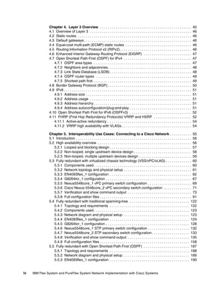
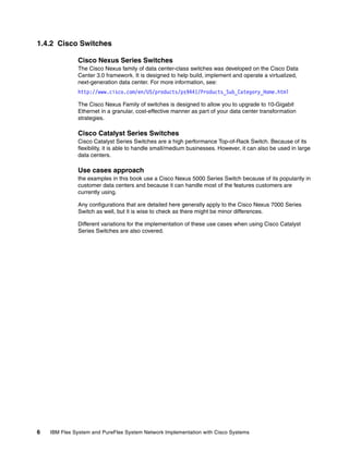
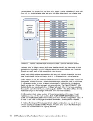
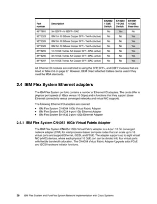
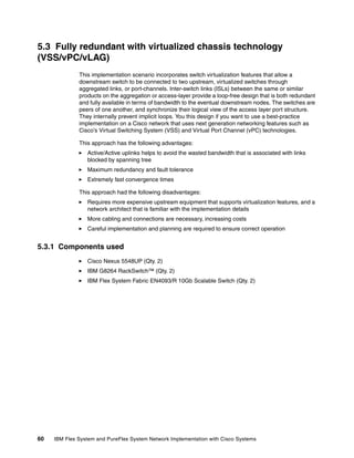
2.4.3 IBM Flex System EN4132 2-port 10Gb Ethernet Adapter
The IBM Flex System EN4132 2-port 10Gb Ethernet Adapter provides the highest-performing
and most flexible interconnect solution for servers used in enterprise data centers,
high-performance computing, and embedded environments.
The IBM Flex System EN4132 2-port 10Gb Ethernet Adapter is shown in Figure 2-26.
Figure 2-26 The EN4132 2-port 10Gb Ethernet Adapter for IBM Flex System](https://image.slidesharecdn.com/ibmflexsystemandpureflexsystemnetworkimplementationwithciscosystems-140711170754-phpapp01/85/Ibm-flex-system-and-pure-flex-system-network-implementation-with-cisco-systems-46-320.jpg)


![Chapter 5. Interoperability Use Cases: Connecting to a Cisco Network 79
INTB6 Operational
INTB7 Operational
INTB8 Operational
INTB9 Operational
INTB10 Operational
INTB11 Operational
INTB12 Operational
INTB13 Operational
INTB14 Operational
Trigger 2: Disabled
Trigger 3: Disabled
Trigger 4: Disabled
Trigger 5: Disabled
Trigger 6: Disabled
Trigger 7: Disabled
Trigger 8: Disabled
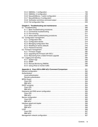
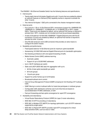
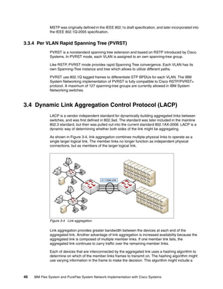
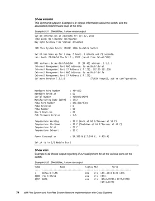
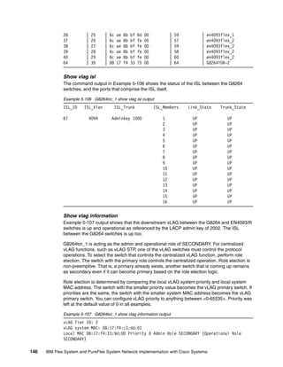
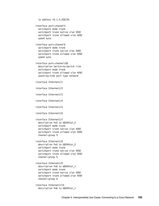
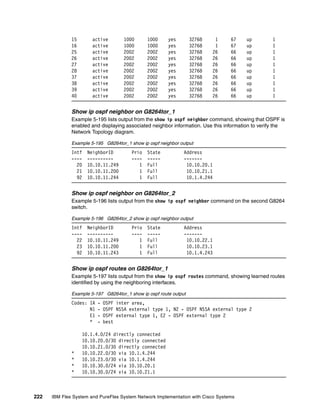
Ping output for equipment on VLAN 4092
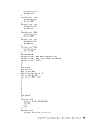
To verify connectivity, issue ping commands to devices on VLAN 4092 (Data VLAN) as shown
in Example 5-40. IP address 10.4.1.10 represents a compute node with an operating system
installed, flex_node1 on the Network Topology diagram.
Example 5-40 Ping verification for equipment on VLAN 4092
en4093flex_1#ping 10.1.4.10 data-port
Connecting via DATA port.
[host 10.1.4.10, max tries 5, delay 1000 msec, length 0, ping source N/S, ttl 255,
tos 0]
10.1.4.10: #1 ok, RTT 1 msec.
10.1.4.10: #2 ok, RTT 0 msec.
10.1.4.10: #3 ok, RTT 1 msec.
10.1.4.10: #4 ok, RTT 0 msec.
10.1.4.10: #5 ok, RTT 0 msec.
Ping finished.
en4093flex_1#ping 10.1.4.239 data-port
Connecting via DATA port.
[host 10.1.4.239, max tries 5, delay 1000 msec, length 0, ping source N/S, ttl
255, tos 0]
10.1.4.239: #1 ok, RTT 4 msec.
10.1.4.239: #2 ok, RTT 1 msec.
10.1.4.239: #3 ok, RTT 2 msec.
10.1.4.239: #4 ok, RTT 3 msec.
10.1.4.239: #5 ok, RTT 1 msec.
Ping finished.
en4093flex_1#ping 10.1.4.243 data-port
Connecting via DATA port.](https://image.slidesharecdn.com/ibmflexsystemandpureflexsystemnetworkimplementationwithciscosystems-140711170754-phpapp01/85/Ibm-flex-system-and-pure-flex-system-network-implementation-with-cisco-systems-93-320.jpg)
![80 IBM Flex System and PureFlex System Network Implementation with Cisco Systems
[host 10.1.4.243, max tries 5, delay 1000 msec, length 0, ping source N/S, ttl
255, tos 0]
10.1.4.243: #1 ok, RTT 1 msec.
10.1.4.243: #2 ok, RTT 1 msec.
10.1.4.243: #3 ok, RTT 2 msec.
10.1.4.243: #4 ok, RTT 8 msec.
10.1.4.243: #5 ok, RTT 6 msec.
Ping finished.
en4093flex_1#ping 10.1.4.244 data-port
Connecting via DATA port.
[host 10.1.4.244, max tries 5, delay 1000 msec, length 0, ping source N/S, ttl
255, tos 0]
10.1.4.244: #1 ok, RTT 1 msec.
10.1.4.244: #2 ok, RTT 2 msec.
10.1.4.244: #3 ok, RTT 1 msec.
10.1.4.244: #4 ok, RTT 2 msec.
10.1.4.244: #5 ok, RTT 0 msec.
Ping finished.
en4093flex_1#ping 10.1.4.249 data-port
Connecting via DATA port.
[host 10.1.4.241, max tries 5, delay 1000 msec, length 0, ping source N/S, ttl
255, tos 0]
10.1.4.241: #1 ok, RTT 2 msec.
10.1.4.241: #2 ok, RTT 1 msec.
10.1.4.241: #3 ok, RTT 2 msec.
10.1.4.241: #4 ok, RTT 1 msec.
10.1.4.241: #5 ok, RTT 3 msec.
Ping finished.
en4093flex_1#ping 10.1.4.200 data-port
Connecting via DATA port.
[host 10.1.4.241, max tries 5, delay 1000 msec, length 0, ping source N/S, ttl
255, tos 0]
10.1.4.241: #1 ok, RTT 2 msec.
10.1.4.241: #2 ok, RTT 2 msec.
10.1.4.241: #3 ok, RTT 2 msec.
10.1.4.241: #4 ok, RTT 1 msec.
10.1.4.241: #5 ok, RTT 3 msec.
Ping finished
G8264 output
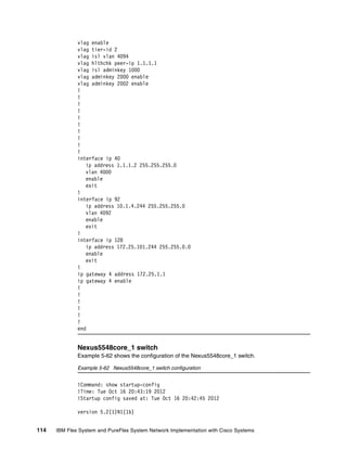
This section lists output from the switch with hostname G8264tor_1. Similar or identical
output exists for the switch with hostname G8264tor_2.
Show version
Example 5-41 output shows information about the switch and the associated code/firmware
level.
Example 5-41 G8264tor_1 show version output
System Information at 20:30:07 Thu Oct 18, 2012
Time zone: No timezone configured
Daylight Savings Time Status: Disabled](https://image.slidesharecdn.com/ibmflexsystemandpureflexsystemnetworkimplementationwithciscosystems-140711170754-phpapp01/85/Ibm-flex-system-and-pure-flex-system-network-implementation-with-cisco-systems-94-320.jpg)


![86 IBM Flex System and PureFlex System Network Implementation with Cisco Systems
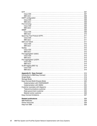
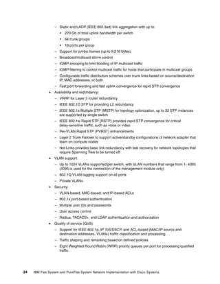
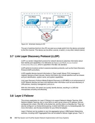
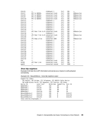
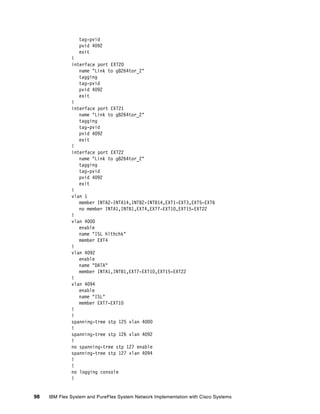
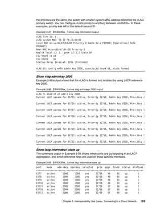
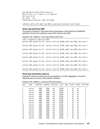
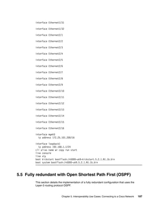
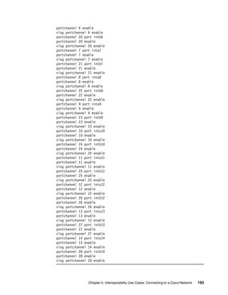
Show lacp information state up
Example 5-49 shows which ports are participating in an LACP aggregation, and which
reference keys are used on those specific interfaces.
Example 5-49 G8264tor_1 show lacp information state up
port mode adminkey operkey selected prio aggr trunk status minlinks
---------------------------------------------------------------------------------
1 active 1000 1000 yes 32768 1 67 up 1
2 active 1000 1000 yes 32768 1 67 up 1
3 active 1000 1000 yes 32768 1 67 up 1
4 active 1000 1000 yes 32768 1 67 up 1
5 active 1000 1000 yes 32768 1 67 up 1
6 active 1000 1000 yes 32768 1 67 up 1
7 active 1000 1000 yes 32768 1 67 up 1
8 active 1000 1000 yes 32768 1 67 up 1
9 active 1000 1000 yes 32768 1 67 up 1
10 active 1000 1000 yes 32768 1 67 up 1
11 active 1000 1000 yes 32768 1 67 up 1
12 active 1000 1000 yes 32768 1 67 up 1
13 active 1000 1000 yes 32768 1 67 up 1
14 active 1000 1000 yes 32768 1 67 up 1
15 active 1000 1000 yes 32768 1 67 up 1
16 active 1000 1000 yes 32768 1 67 up 1
18 active 2000 2000 yes 32768 20 65 up 1
20 active 2000 2000 yes 32768 20 65 up 1
22 active 2000 2000 yes 32768 20 65 up 1
24 active 2000 2000 yes 32768 20 65 up 1
25 active 2002 2002 yes 32768 26 66 up 1
26 active 2002 2002 yes 32768 26 66 up 1
27 active 2002 2002 yes 32768 26 66 up 1
28 active 2002 2002 yes 32768 26 66 up 1
37 active 2002 2002 yes 32768 26 66 up 1
38 active 2002 2002 yes 32768 26 66 up 1
39 active 2002 2002 yes 32768 26 66 up 1
40 active 2002 2002 yes 32768 26 66 up 1
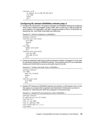
Ping output for equipment on VLAN 4092
To verify connectivity, issue ping commands to devices on VLAN 4092 (Data VLAN) as shown
in Example 5-50. IP address 10.4.1.10 represents a compute node with an operating system
installed, flex_node1 on the Network Topology diagram.
Example 5-50 Ping verification for equipment on VLAN 4092
G8264TOR-1#ping 10.1.4.10 data-port
Connecting via DATA port.
[host 10.1.4.10, max tries 5, delay 1000 msec, length 0, ping source N/S, ttl 255,
tos 0]
10.1.4.10: #1 ok, RTT 1 msec.
10.1.4.10: #2 ok, RTT 0 msec.
10.1.4.10: #3 ok, RTT 0 msec.
10.1.4.10: #4 ok, RTT 0 msec.
10.1.4.10: #5 ok, RTT 0 msec.
Ping finished.
G8264TOR-1#ping 10.1.4.249 data-port](https://image.slidesharecdn.com/ibmflexsystemandpureflexsystemnetworkimplementationwithciscosystems-140711170754-phpapp01/85/Ibm-flex-system-and-pure-flex-system-network-implementation-with-cisco-systems-100-320.jpg)
![Chapter 5. Interoperability Use Cases: Connecting to a Cisco Network 87
Connecting via DATA port.
[host 10.1.4.249, max tries 5, delay 1000 msec, length 0, ping source N/S, ttl
255, tos 0]
10.1.4.249: #1 ok, RTT 1 msec.
10.1.4.249: #2 ok, RTT 0 msec.
10.1.4.249: #3 ok, RTT 1 msec.
10.1.4.249: #4 ok, RTT 0 msec.
10.1.4.249: #5 ok, RTT 0 msec.
Ping finished.
G8264TOR-1#ping 10.1.4.238 data-port
Connecting via DATA port.
[host 10.1.4.238, max tries 5, delay 1000 msec, length 0, ping source N/S, ttl
255, tos 0]
10.1.4.238: #1 ok, RTT 4 msec.
10.1.4.238: #2 ok, RTT 1 msec.
10.1.4.238: #3 ok, RTT 1 msec.
10.1.4.238: #4 ok, RTT 1 msec.
10.1.4.238: #5 ok, RTT 0 msec.
Ping finished.
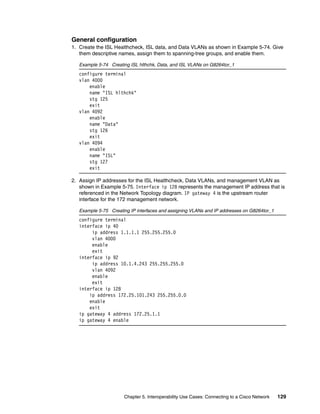
Nexus output
This section lists output from the switch with hostname Nexus5548core_1. Similar or identical
output exists for the switch with hostname Nexus5548core_2.
Show version
The output in Example 5-51 shows information about the switch and the associated
code/firmware level.
Example 5-51 Nexus5548core_1 show version output
Cisco Nexus Operating System (NX-OS) Software
TAC support: http://www.cisco.com/tac
Documents: http://www.cisco.com/en/US/products/ps9372/tsd_products_support_serie
s_home.html
Copyright (c) 2002-2012, Cisco Systems, Inc. All rights reserved.
The copyrights to certain works contained herein are owned by
other third parties and are used and distributed under license.
Some parts of this software are covered under the GNU Public
License. A copy of the license is available at
http://www.gnu.org/licenses/gpl.html.
Software
BIOS: version 3.5.0
loader: version N/A
kickstart: version 5.2(1)N1(1b)
system: version 5.2(1)N1(1b)
power-seq: Module 1: version v1.0
Module 3: version v5.0
uC: version v1.2.0.1
SFP uC: Module 1: v1.0.0.0
BIOS compile time: 02/03/2011
kickstart image file is: bootflash:///n5000-uk9-kickstart.5.2.1.N1.1b.bin
kickstart compile time: 9/17/2012 11:00:00 [09/17/2012 18:38:53]](https://image.slidesharecdn.com/ibmflexsystemandpureflexsystemnetworkimplementationwithciscosystems-140711170754-phpapp01/85/Ibm-flex-system-and-pure-flex-system-network-implementation-with-cisco-systems-101-320.jpg)
![88 IBM Flex System and PureFlex System Network Implementation with Cisco Systems
system image file is: bootflash:///n5000-uk9.5.2.1.N1.1b.bin
system compile time: 9/17/2012 11:00:00 [09/17/2012 20:38:22]
Hardware
cisco Nexus5548 Chassis ("O2 32X10GE/Modular Universal Platform Supervisor")
Intel(R) Xeon(R) CPU with 8263848 kB of memory.
Processor Board ID FOC15424504
Device name: Nexus5548core_1
bootflash: 2007040 kB
Kernel uptime is 0 day(s), 22 hour(s), 32 minute(s), 3 second(s)
Last reset
Reason: Unknown
System version: 5.2(1)N1(1b)
Service:
plugin
Core Plugin, Ethernet Plugin
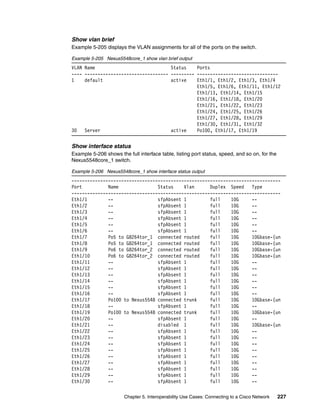
Show vlan
Example 5-52 displays the VLAN assignments for all of the ports on the switch.
Example 5-52 Nexus5548core_1 show vlan output
VLAN Name Status Ports
---- -------------------------------- --------- -------------------------------
1 default active Eth1/1, Eth1/2, Eth1/3, Eth1/4
Eth1/5, Eth1/6, Eth1/11, Eth1/12
Eth1/13, Eth1/14, Eth1/15
Eth1/16, Eth1/18, Eth1/20
Eth1/22, Eth1/23, Eth1/24
Eth1/25, Eth1/26, Eth1/27
Eth1/28, Eth1/29, Eth1/30
Eth1/31, Eth1/32
1000 vPC_PEER_LINK active Eth1/21
4092 DATA_VLAN active Po5, Po100, Eth1/7, Eth1/8
Eth1/9, Eth1/10, Eth1/17
Eth1/19
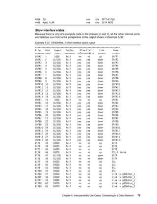
Show interface status
Example 5-53 shows the full interface table, listing port status, speed, and so on.
Example 5-53 Nexus5548core_1 show interface status output
--------------------------------------------------------------------------------
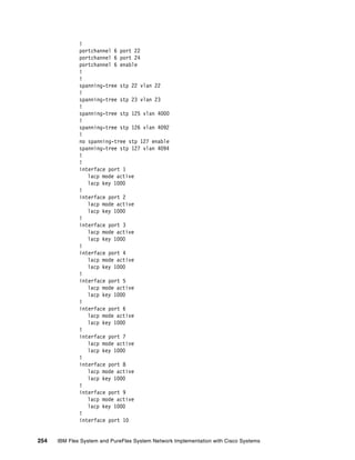
Port Name Status Vlan Duplex Speed Type
--------------------------------------------------------------------------------
Eth1/1 -- sfpAbsent 1 full 10G --
Eth1/2 -- sfpAbsent 1 full 10G --
Eth1/3 -- sfpAbsent 1 full 10G --
Eth1/4 -- sfpAbsent 1 full 10G --
Eth1/5 -- sfpAbsent 1 full 10G --](https://image.slidesharecdn.com/ibmflexsystemandpureflexsystemnetworkimplementationwithciscosystems-140711170754-phpapp01/85/Ibm-flex-system-and-pure-flex-system-network-implementation-with-cisco-systems-102-320.jpg)


![Chapter 5. Interoperability Use Cases: Connecting to a Cisco Network 141
INTB8 Operational
INTB9 Operational
INTB10 Operational
INTB11 Operational
INTB12 Operational
INTB13 Operational
INTB14 Operational
Trigger 2: Disabled
Trigger 3: Disabled
Trigger 4: Disabled
Trigger 5: Disabled
Trigger 6: Disabled
Trigger 7: Disabled
Trigger 8: Disabled
Ping output for equipment on VLAN 4092
To verify connectivity, issue ping commands to devices on VLAN 4092 (Data VLAN) as shown
in Example 5-101. IP address 10.4.1.10 represents a Compute Node with an operating
system installed, flex_node1 on the Network Topology diagram.
Example 5-101 Ping verification for equipment on VLAN 4092
en4093flex_1#ping 10.1.4.10 data-port
Connecting via DATA port.
[host 10.1.4.10, max tries 5, delay 1000 msec, length 0, ping source N/S, ttl 255,
tos 0]
10.1.4.10: #1 ok, RTT 1 msec.
10.1.4.10: #2 ok, RTT 0 msec.
10.1.4.10: #3 ok, RTT 1 msec.
10.1.4.10: #4 ok, RTT 0 msec.
10.1.4.10: #5 ok, RTT 0 msec.
Ping finished.
en4093flex_1#ping 10.1.4.239 data-port
Connecting via DATA port.
[host 10.1.4.239, max tries 5, delay 1000 msec, length 0, ping source N/S, ttl
255, tos 0]
10.1.4.239: #1 ok, RTT 4 msec.
10.1.4.239: #2 ok, RTT 1 msec.
10.1.4.239: #3 ok, RTT 2 msec.
10.1.4.239: #4 ok, RTT 3 msec.
10.1.4.239: #5 ok, RTT 1 msec.
Ping finished.
en4093flex_1#ping 10.1.4.243 data-port
Connecting via DATA port.
[host 10.1.4.243, max tries 5, delay 1000 msec, length 0, ping source N/S, ttl
255, tos 0]](https://image.slidesharecdn.com/ibmflexsystemandpureflexsystemnetworkimplementationwithciscosystems-140711170754-phpapp01/85/Ibm-flex-system-and-pure-flex-system-network-implementation-with-cisco-systems-155-320.jpg)
![142 IBM Flex System and PureFlex System Network Implementation with Cisco Systems
10.1.4.243: #1 ok, RTT 1 msec.
10.1.4.243: #2 ok, RTT 1 msec.
10.1.4.243: #3 ok, RTT 2 msec.
10.1.4.243: #4 ok, RTT 8 msec.
10.1.4.243: #5 ok, RTT 6 msec.
Ping finished.
en4093flex_1#ping 10.1.4.244 data-port
Connecting via DATA port.
[host 10.1.4.244, max tries 5, delay 1000 msec, length 0, ping source N/S, ttl
255, tos 0]
10.1.4.244: #1 ok, RTT 1 msec.
10.1.4.244: #2 ok, RTT 2 msec.
10.1.4.244: #3 ok, RTT 1 msec.
10.1.4.244: #4 ok, RTT 2 msec.
10.1.4.244: #5 ok, RTT 0 msec.
Ping finished.
en4093flex_1#ping 10.1.4.249 data-port
Connecting via DATA port.
[host 10.1.4.241, max tries 5, delay 1000 msec, length 0, ping source N/S, ttl
255, tos 0]
10.1.4.241: #1 ok, RTT 2 msec.
10.1.4.241: #2 ok, RTT 1 msec.
10.1.4.241: #3 ok, RTT 2 msec.
10.1.4.241: #4 ok, RTT 1 msec.
10.1.4.241: #5 ok, RTT 3 msec.
Ping finished.
en4093flex_1#ping 10.1.4.200 data-port
Connecting via DATA port.
[host 10.1.4.241, max tries 5, delay 1000 msec, length 0, ping source N/S, ttl
255, tos 0]
10.1.4.241: #1 ok, RTT 2 msec.
10.1.4.241: #2 ok, RTT 2 msec.
10.1.4.241: #3 ok, RTT 2 msec.
10.1.4.241: #4 ok, RTT 1 msec.
10.1.4.241: #5 ok, RTT 3 msec.
Ping finished
G8264 output
This section lists output from the switch with hostname G8264tor_1. Similar or identical
output exists for the switch with hostname G8264tor_2 unless otherwise noted.
Show version
Example 5-102 shows information about the switch used, and the associated code/firmware
level.
Example 5-102 G8264tor_1 show version output
System Information at 20:30:07 Thu Oct 18, 2012
Time zone: No timezone configured
Daylight Savings Time Status: Disabled
IBM Networking Operating System RackSwitch G8264](https://image.slidesharecdn.com/ibmflexsystemandpureflexsystemnetworkimplementationwithciscosystems-140711170754-phpapp01/85/Ibm-flex-system-and-pure-flex-system-network-implementation-with-cisco-systems-156-320.jpg)


![Chapter 5. Interoperability Use Cases: Connecting to a Cisco Network 153
------------- ---- ---------- ----- ---- ---------------------- -------- -------
MGT 0 0 FWD *
* = STP turned off for this port.
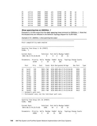
Ping output for equipment on VLAN 4092
To verify connectivity, issue ping commands to devices on VLAN 4092 (Data VLAN) as shown
in Example 5-112. IP address 10.4.1.10 represents a compute node with an operating
system installed, flex_node1 on the Network Topology diagram.
Example 5-112 Ping verification for equipment on VLAN 4092
G8264TOR-1#ping 10.1.4.249 data-port
Connecting via DATA port.
[host 10.1.4.249, max tries 5, delay 1000 msec, length 0, ping source N/S, ttl
255, tos 0]
10.1.4.249: #1 ok, RTT 0 msec.
10.1.4.249: #2 ok, RTT 0 msec.
10.1.4.249: #3 ok, RTT 0 msec.
10.1.4.249: #4 ok, RTT 0 msec.
10.1.4.249: #5 ok, RTT 0 msec.
Ping finished.
G8264TOR-1#ping 10.1.4.238 data-port
Connecting via DATA port.
[host 10.1.4.238, max tries 5, delay 1000 msec, length 0, ping source N/S, ttl
255, tos 0]
10.1.4.238: #1 ok, RTT 4 msec.
10.1.4.238: #2 ok, RTT 2 msec.
10.1.4.238: #3 ok, RTT 0 msec.
10.1.4.238: #4 ok, RTT 1 msec.
10.1.4.238: #5 ok, RTT 1 msec.
Ping finished.
G8264TOR-1#ping 10.1.4.10 data-port
Connecting via DATA port.
[host 10.1.4.10, max tries 5, delay 1000 msec, length 0, ping source N/S, ttl 255,
tos 0]
10.1.4.10: #1 ok, RTT 0 msec.
10.1.4.10: #2 ok, RTT 0 msec.
10.1.4.10: #3 ok, RTT 0 msec.
10.1.4.10: #4 ok, RTT 0 msec.
10.1.4.10: #5 ok, RTT 0 msec.
Ping finished.
Nexus output
This section lists output from the switch with hostname Nexus5548core_1. Similar or identical
output exists for the switch with hostname Nexus5548core_2 unless otherwise noted.](https://image.slidesharecdn.com/ibmflexsystemandpureflexsystemnetworkimplementationwithciscosystems-140711170754-phpapp01/85/Ibm-flex-system-and-pure-flex-system-network-implementation-with-cisco-systems-167-320.jpg)
![154 IBM Flex System and PureFlex System Network Implementation with Cisco Systems
Show version
Example 5-113 shows information about the switch, and the associated code/firmware level.
Example 5-113 Nexus5548core_1 show version output
Cisco Nexus Operating System (NX-OS) Software
TAC support: http://www.cisco.com/tac
Documents: http://www.cisco.com/en/US/products/ps9372/tsd_products_support_serie
s_home.html
Copyright (c) 2002-2012, Cisco Systems, Inc. All rights reserved.
The copyrights to certain works contained herein are owned by
other third parties and are used and distributed under license.
Some parts of this software are covered under the GNU Public
License. A copy of the license is available at
http://www.gnu.org/licenses/gpl.html.
Software
BIOS: version 3.5.0
loader: version N/A
kickstart: version 5.2(1)N1(1b)
system: version 5.2(1)N1(1b)
power-seq: Module 1: version v1.0
Module 3: version v5.0
uC: version v1.2.0.1
SFP uC: Module 1: v1.0.0.0
BIOS compile time: 02/03/2011
kickstart image file is: bootflash:///n5000-uk9-kickstart.5.2.1.N1.1b.bin
kickstart compile time: 9/17/2012 11:00:00 [09/17/2012 18:38:53]
system image file is: bootflash:///n5000-uk9.5.2.1.N1.1b.bin
system compile time: 9/17/2012 11:00:00 [09/17/2012 20:38:22]
Hardware
cisco Nexus5548 Chassis ("O2 32X10GE/Modular Universal Platform Supervisor")
Intel(R) Xeon(R) CPU with 8263848 kB of memory.
Processor Board ID FOC15424504
Device name: Nexus5548core_1
bootflash: 2007040 kB
Kernel uptime is 0 day(s), 22 hour(s), 32 minute(s), 3 second(s)
Last reset
Reason: Unknown
System version: 5.2(1)N1(1b)
Service:
plugin
Core Plugin, Ethernet Plugin](https://image.slidesharecdn.com/ibmflexsystemandpureflexsystemnetworkimplementationwithciscosystems-140711170754-phpapp01/85/Ibm-flex-system-and-pure-flex-system-network-implementation-with-cisco-systems-168-320.jpg)


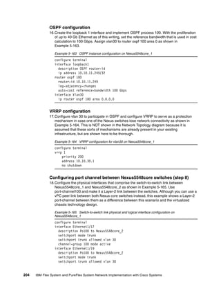


![214 IBM Flex System and PureFlex System Network Implementation with Cisco Systems
mac-address 00-00-5e-00-01-xx where xx is defined by the vrrp virtual-router-id that is
defined as 01 as shown in Example 5-183.
Example 5-183 EN4093flex_1 show ARP output
en4093flex_1#show arp
Current ARP configuration:
rearp 5
No static ARP configured.
------------------------------------------------------------------
Total number of arp entries : 6
IP address Flags MAC address VLAN Age Port
--------------- ----- ----------------- ------ --- ----
1.1.1.1 P 6c:ae:8b:bf:6d:00 4000
1.1.1.2 6c:ae:8b:bf:fe:00 4000 11 EXT4
10.1.4.238 P 6c:ae:8b:bf:6d:00 4092
10.1.4.241 00:00:5e:00:01:01 4092 1 TRK65
10.1.4.243 08:17:f4:33:9d:00 4092 287 TRK65
10.1.4.244 08:17:f4:33:75:00 4092 279 TRK65
Ping output for equipment on VLAN 4092
To verify connectivity, issue ping commands to devices on VLAN 4092 (Data VLAN) as shown
in Example 5-184. IP address 10.4.1.10 represents a compute node with an operating
system installed, flex_node1 on the Network Topology diagram.
Example 5-184 Ping verification for equipment on VLAN 4092
en4093flex_1#ping 10.1.4.10 data-port
Connecting via DATA port.
[host 10.1.4.10, max tries 5, delay 1000 msec, length 0, ping source N/S, ttl 255,
tos 0]
10.1.4.10: #1 ok, RTT 1 msec.
10.1.4.10: #2 ok, RTT 0 msec.
10.1.4.10: #3 ok, RTT 1 msec.
10.1.4.10: #4 ok, RTT 0 msec.
10.1.4.10: #5 ok, RTT 0 msec.
Ping finished.
en4093flex_1#ping 10.1.4.239 data-port
Connecting via DATA port.
[host 10.1.4.239, max tries 5, delay 1000 msec, length 0, ping source N/S, ttl
255, tos 0]
10.1.4.239: #1 ok, RTT 4 msec.
10.1.4.239: #2 ok, RTT 1 msec.
10.1.4.239: #3 ok, RTT 2 msec.
10.1.4.239: #4 ok, RTT 3 msec.
10.1.4.239: #5 ok, RTT 1 msec.
Ping finished.
en4093flex_1#ping 10.1.4.243 data-port
Connecting via DATA port.
[host 10.1.4.243, max tries 5, delay 1000 msec, length 0, ping source N/S, ttl
255, tos 0]
10.1.4.243: #1 ok, RTT 1 msec.
10.1.4.243: #2 ok, RTT 1 msec.
10.1.4.243: #3 ok, RTT 2 msec.](https://image.slidesharecdn.com/ibmflexsystemandpureflexsystemnetworkimplementationwithciscosystems-140711170754-phpapp01/85/Ibm-flex-system-and-pure-flex-system-network-implementation-with-cisco-systems-228-320.jpg)
![Chapter 5. Interoperability Use Cases: Connecting to a Cisco Network 215
10.1.4.243: #4 ok, RTT 8 msec.
10.1.4.243: #5 ok, RTT 6 msec.
Ping finished.
en4093flex_1#ping 10.1.4.244 data-port
Connecting via DATA port.
[host 10.1.4.244, max tries 5, delay 1000 msec, length 0, ping source N/S, ttl
255, tos 0]
10.1.4.244: #1 ok, RTT 1 msec.
10.1.4.244: #2 ok, RTT 2 msec.
10.1.4.244: #3 ok, RTT 1 msec.
10.1.4.244: #4 ok, RTT 2 msec.
10.1.4.244: #5 ok, RTT 0 msec.
Ping finished.
en4093flex_1#ping 10.1.4.249 data-port
Connecting via DATA port.
[host 10.1.4.241, max tries 5, delay 1000 msec, length 0, ping source N/S, ttl
255, tos 0]
10.1.4.241: #1 ok, RTT 2 msec.
10.1.4.241: #2 ok, RTT 1 msec.
10.1.4.241: #3 ok, RTT 2 msec.
10.1.4.241: #4 ok, RTT 1 msec.
10.1.4.241: #5 ok, RTT 3 msec.
Ping finished.
en4093flex_1#ping 10.1.4.200 data-port
Connecting via DATA port.
[host 10.1.4.241, max tries 5, delay 1000 msec, length 0, ping source N/S, ttl
255, tos 0]
10.1.4.241: #1 ok, RTT 2 msec.
10.1.4.241: #2 ok, RTT 2 msec.
10.1.4.241: #3 ok, RTT 2 msec.
10.1.4.241: #4 ok, RTT 1 msec.
10.1.4.241: #5 ok, RTT 3 msec.
Ping finished
G8264 output
This section lists output from the switch with hostname G8264tor_1, noting specific
differences on G8264tor_2 when applicable.
Show version
Example 5-185 shows information about the switch and the associated code/firmware level.
Example 5-185 G8264tor_1 show version output
System Information at 21:55:21 Wed Oct 24, 2012
Time zone: No timezone configured
Daylight Savings Time Status: Disabled
IBM Networking Operating System RackSwitch G8264
Switch has been up for 0 days, 3 hours, 55 minutes and 35 seconds.
Last boot: 18:01:02 Wed Oct 24, 2012 (reset from Telnet/SSH)](https://image.slidesharecdn.com/ibmflexsystemandpureflexsystemnetworkimplementationwithciscosystems-140711170754-phpapp01/85/Ibm-flex-system-and-pure-flex-system-network-implementation-with-cisco-systems-229-320.jpg)


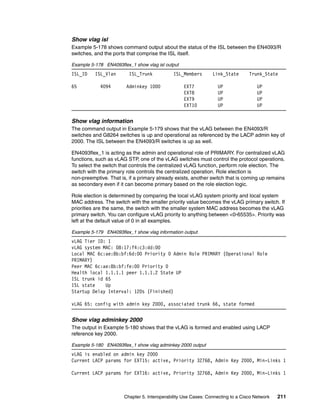
![Chapter 5. Interoperability Use Cases: Connecting to a Cisco Network 225
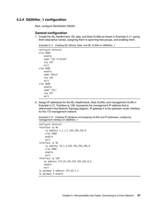
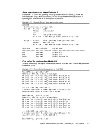
Ping output for equipment on VLAN 4092
To verify connectivity, issue ping commands to devices on VLAN 4092 (Data VLAN) in
Example 5-203. IP address 10.4.1.10 represents a compute node with an operating system
installed, flex_node1 on the Network Topology diagram. IP address 10.10.30.1 represents
the VIP on the Nexus pair simulating the Server network.
Example 5-203 Ping verification for equipment on VLAN 4092
G8264TOR-1#ping 10.10.30.1 data-port
Connecting via DATA port.
[host 10.10.30.1, max tries 5, delay 1000 msec, length 0, ping source N/S, ttl
255, tos 0]
10.10.30.1: #1 ok, RTT 1 msec.
10.10.30.1: #2 ok, RTT 0 msec.
10.10.30.1: #3 ok, RTT 0 msec.
10.10.30.1: #4 ok, RTT 0 msec.
10.10.30.1: #5 ok, RTT 1 msec.
Ping finished.
G8264TOR-1#
G8264TOR-1#ping 10.1.4.238 data-port
Connecting via DATA port.
[host 10.1.4.238, max tries 5, delay 1000 msec, length 0, ping source N/S, ttl
255, tos 0]
10.1.4.238: #1 ok, RTT 7 msec.
10.1.4.238: #2 ok, RTT 3 msec.
10.1.4.238: #3 ok, RTT 2 msec.
10.1.4.238: #4 ok, RTT 1 msec.
10.1.4.238: #5 ok, RTT 0 msec.
Ping finished.
G8264TOR-1#
G8264TOR-1#ping 10.1.4.239 data-port
Connecting via DATA port.
[host 10.1.4.239, max tries 5, delay 1000 msec, length 0, ping source N/S, ttl
255, tos 0]
10.1.4.239: #1 ok, RTT 5 msec.
10.1.4.239: #2 ok, RTT 0 msec.
10.1.4.239: #3 ok, RTT 13 msec.
10.1.4.239: #4 ok, RTT 0 msec.
10.1.4.239: #5 ok, RTT 0 msec.
Ping finished.
G8264TOR-1#
G8264TOR-1#ping 10.1.4.10 data-port
Connecting via DATA port.
[host 10.1.4.10, max tries 5, delay 1000 msec, length 0, ping source N/S, ttl 255,
tos 0]
10.1.4.10: #1 ok, RTT 2 msec.
10.1.4.10: #2 ok, RTT 0 msec.
10.1.4.10: #3 ok, RTT 0 msec.
10.1.4.10: #4 ok, RTT 0 msec.
10.1.4.10: #5 ok, RTT 0 msec.
Ping finished.](https://image.slidesharecdn.com/ibmflexsystemandpureflexsystemnetworkimplementationwithciscosystems-140711170754-phpapp01/85/Ibm-flex-system-and-pure-flex-system-network-implementation-with-cisco-systems-239-320.jpg)
![226 IBM Flex System and PureFlex System Network Implementation with Cisco Systems
Nexus output
This section lists output from the switch with hostname Nexus5548core_1. Similar or identical
output exists for the switch with hostname Nexus5548core_2 unless otherwise noted.
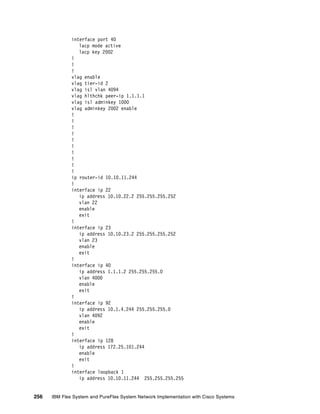
Show version
Example 5-204 shows information about the switch and the associated code/firmware level.
Example 5-204 Nexus5548core_1 show version output
Cisco Nexus Operating System (NX-OS) Software
TAC support: http://www.cisco.com/tac
Documents: http://www.cisco.com/en/US/products/ps9372/tsd_products_support_serie
s_home.html
Copyright (c) 2002-2012, Cisco Systems, Inc. All rights reserved.
The copyrights to certain works contained herein are owned by
other third parties and are used and distributed under license.
Some parts of this software are covered under the GNU Public
License. A copy of the license is available at
http://www.gnu.org/licenses/gpl.html.
Software
BIOS: version 3.5.0
loader: version N/A
kickstart: version 5.2(1)N1(1b)
system: version 5.2(1)N1(1b)
power-seq: Module 1: version v1.0
Module 3: version v5.0
uC: version v1.2.0.1
SFP uC: Module 1: v1.0.0.0
BIOS compile time: 02/03/2011
kickstart image file is: bootflash:///n5000-uk9-kickstart.5.2.1.N1.1b.bin
kickstart compile time: 9/17/2012 11:00:00 [09/17/2012 18:38:53]
system image file is: bootflash:///n5000-uk9.5.2.1.N1.1b.bin
system compile time: 9/17/2012 11:00:00 [09/17/2012 20:38:22]
Hardware
cisco Nexus5548 Chassis ("O2 32X10GE/Modular Universal Platform Supervisor")
Intel(R) Xeon(R) CPU with 8263848 kB of memory.
Processor Board ID FOC15424504
Device name: Nexus5548core_1
bootflash: 2007040 kB
Kernel uptime is 0 day(s), 22 hour(s), 32 minute(s), 3 second(s)
Last reset
Reason: Unknown
System version: 5.2(1)N1(1b)
Service:
plugin
Core Plugin, Ethernet Plugin](https://image.slidesharecdn.com/ibmflexsystemandpureflexsystemnetworkimplementationwithciscosystems-140711170754-phpapp01/85/Ibm-flex-system-and-pure-flex-system-network-implementation-with-cisco-systems-240-320.jpg)

![230 IBM Flex System and PureFlex System Network Implementation with Cisco Systems
Hello timer due in 00:00:02
No authentication
Number of opaque link LSAs: 0, checksum sum 0
Vlan30 is up, line protocol is up
IP address 10.10.30.3/24, Process ID 100 VRF default, area 0.0.0.0
Enabled by interface configuration
State BDR, Network type BROADCAST, cost 100
Index 3, Transmit delay 1 sec, Router Priority 1
Designated Router ID: 10.10.11.249, address: 10.10.30.2
Backup Designated Router ID: 10.10.11.200, address: 10.10.30.3
1 Neighbors, flooding to 1, adjacent with 1
Timer intervals: Hello 10, Dead 40, Wait 40, Retransmit 5
Hello timer due in 00:00:04
No authentication
Number of opaque link LSAs: 0, checksum sum 0
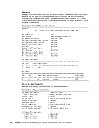
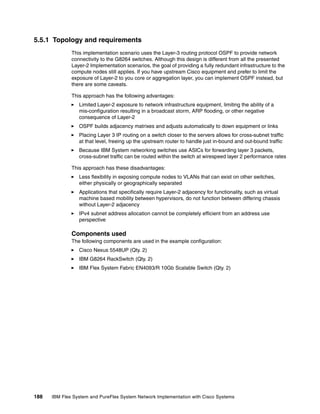
Show ip ospf neighbor on Nexus5548core_1
Example 5-211 displays the OSPF neighbor data from the perspective of the
Nexus5548core_1 switch.
Example 5-211 Nexus5548core_1 show ip ospf neighbor output
OSPF Process ID 100 VRF default
Total number of neighbors: 3
Neighbor ID Pri State Up Time Address Interface
10.10.11.200 1 FULL/BDR 00:06:16 10.10.30.3 Vlan30
10.10.11.243 1 FULL/BDR 02:36:17 10.10.20.2 Po5
10.10.11.244 1 FULL/BDR 02:34:32 10.10.22.2 Po6
Show ip ospf neighbor on Nexus5548core_2
Example 5-212 displays the OSPF neighbor data from the perspective of the
Nexus5548core_2 switch.
Example 5-212 Nexus5548core_2 show ip ospf neighbor output
OSPF Process ID 100 VRF default
Total number of neighbors: 3
Neighbor ID Pri State Up Time Address Interface
10.10.11.244 1 FULL/DR 01:43:06 10.10.23.2 Po5
10.10.11.243 1 FULL/DR 01:42:14 10.10.21.2 Po6
10.10.11.249 1 FULL/DR 00:06:19 10.10.30.2 Vlan30
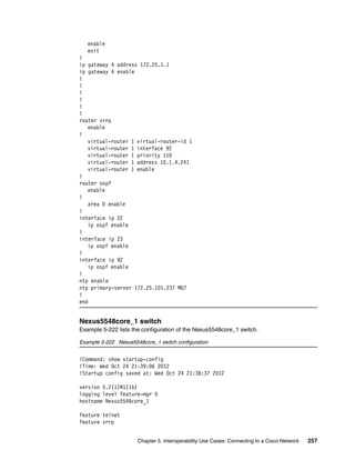
Show ip route ospf for Nexus5548core_1
Example 5-213 lists routes that were learned by using OSPF for Nexus5548core_1.
Example 5-213 Nexus5548core_1 show ip route ospf output
IP Route Table for VRF "default"
'*' denotes best ucast next-hop
'**' denotes best mcast next-hop
'[x/y]' denotes [preference/metric]
10.1.4.0/24, ubest/mbest: 2/0
*via 10.10.20.2, Po5, [110/6], 02:37:43, ospf-100, intra
*via 10.10.22.2, Po6, [110/6], 02:36:08, ospf-100, intra](https://image.slidesharecdn.com/ibmflexsystemandpureflexsystemnetworkimplementationwithciscosystems-140711170754-phpapp01/85/Ibm-flex-system-and-pure-flex-system-network-implementation-with-cisco-systems-244-320.jpg)
![Chapter 5. Interoperability Use Cases: Connecting to a Cisco Network 231
10.10.21.0/30, ubest/mbest: 1/0
*via 10.10.20.2, Po5, [110/6], 02:16:35, ospf-100, intra
10.10.23.0/30, ubest/mbest: 1/0
*via 10.10.22.2, Po6, [110/6], 02:16:35, ospf-100, intra
Show ip route ospf for Nexus5548core_2
Example 5-214 lists routes that were learned by using OSPF for Nexus5548core_2.
Example 5-214 Nexus5548core_2 show ip route ospf output
IP Route Table for VRF "default"
'*' denotes best ucast next-hop
'**' denotes best mcast next-hop
'[x/y]' denotes [preference/metric]
10.1.4.0/24, ubest/mbest: 2/0
*via 10.10.21.2, Po6, [110/6], 01:43:43, ospf-100, intra
*via 10.10.23.2, Po5, [110/6], 01:44:36, ospf-100, intra
10.10.20.0/30, ubest/mbest: 1/0
*via 10.10.21.2, Po6, [110/6], 01:43:43, ospf-100, intra
10.10.22.0/30, ubest/mbest: 1/0
*via 10.10.23.2, Po5, [110/6], 01:44:36, ospf-100, intra
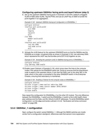
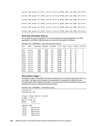
Show vrrp detail for Nexus5548core_1
To simulate the Server VLAN, output for the running VRRP process on Nexus5548core_1 is
listed in Example 5-215.
Example 5-215 Nexus5548core_1 show vrrp detail output
Vlan30 - Group 1 (IPV4)
State is Master
Virtual IP address is 10.10.30.1
Priority 200, Configured 200
Forwarding threshold(for VPC), lower: 1 upper: 200
Advertisement interval 1
Preemption enabled
Virtual MAC address is 0000.5e00.0101
Master router is Local
Show vrrp detail for Nexus5548core_2
Example 5-216 shows the output for the running VRRP process on Nexus5548core_2. Notice
that the virtual MAC address is the same across both switches.
Example 5-216 Nexus5548core_2 show vrrp detail output
Vlan30 - Group 1 (IPV4)
State is Backup
Virtual IP address is 10.10.30.1
Priority 150, Configured 150
Forwarding threshold(for VPC), lower: 1 upper: 150
Advertisement interval 1
Preemption enabled
Virtual MAC address is 0000.5e00.0101
Master router is 10.10.30.2](https://image.slidesharecdn.com/ibmflexsystemandpureflexsystemnetworkimplementationwithciscosystems-140711170754-phpapp01/85/Ibm-flex-system-and-pure-flex-system-network-implementation-with-cisco-systems-245-320.jpg)


![270 IBM Flex System and PureFlex System Network Implementation with Cisco Systems
6.1.2 Connectivity troubleshooting
This section contains basic information about how to troubleshoot the IP connectivity in a
network built on IBM System Networking switches. IBM switches come with a set of simple
tools that can be helpful for troubleshooting IP connectivity issues.
Ping
The ping command is a simple tool, based on a request-response mechanism, to verify
connectivity to a remote network node. The ping command is based on ICMP. The request is
an ICMP Echo packet, and the reply is an ICMP Echo Reply. Like a regular IP packet, an
ICMP packet is forwarded based on the intermediate routers’ routing table until it reaches the
destination. After it reaches the destination, the ICMP Echo Reply packet is generated and
forwarded back to the originating node.
Example 6-1 shows the use of ping command to verify connectivity between the switch and
IP address 172.25.101.237.
Example 6-1 Ping command example
en4093flex_1#ping 172.25.101.237
Connecting via MGT port.
[host 172.25.101.237, max tries 5, delay 1000 msec, length 0, ping
source N/S, ttl 255, tos 0]
172.25.101.237: #1 ok, RTT 1 msec.
172.25.101.237: #2 ok, RTT 2 msec.
172.25.101.237: #3 ok, RTT 2 msec.
172.25.101.237: #4 ok, RTT 1 msec.
172.25.101.237: #5 ok, RTT 2 msec.
Ping finished.
You can see in the output that all five ICMP Echo requests received the replies. There is also
more information about the Round Trip Time (RTT), that is, the time it took for the switch to
receive response.
Traceroute
You can use the traceroute command to not only verify connectivity to a remote network
node, but to track the responses from intermediate nodes as well. This action is done by using
the time to live (TTL) field in IP packets. The traceroute command sends a UDP packet to a
port that is not likely to be used on a remote node with a TTL of 1. After the packet reaches
the intermediate router, the TTL is decremented. The ICMP time-exceeded message is then
sent back to the originating node, which increments the TTL to 2, and the process repeats.
After the UDP packet reaches a destination host, an ICMP port-unreachable message is sent
back to the sender. This action provides the sender with information about all intermediate
routers on the way to the destination.
Important: In IBM switches, ping sends an ICMP Echo packet on the management
interface first. If you want to change that option, you must add the data-port keyword to a
command as a parameter.](https://image.slidesharecdn.com/ibmflexsystemandpureflexsystemnetworkimplementationwithciscosystems-140711170754-phpapp01/85/Ibm-flex-system-and-pure-flex-system-network-implementation-with-cisco-systems-284-320.jpg)
![Chapter 6. Troubleshooting and maintenance 271
The command shown in Example 6-2 verifies which hops are on the way from switch to the
system with IP address 10.0.100.1.
Example 6-2 Traceroute command example
ACC-2#traceroute 10.0.100.1 data-port
Connecting via DATA port.
[host 10.0.100.1, max-hops 32, delay 2048 msec]
1 10.0.100.1 0 ms
Trace host responded.
From the output, you see that there is only one hop on the way from switch to destination.
OSPF in this network, which selects this path as the shortest one.
For test purposes, shut down the direct link between the switch and target system and run
traceroute again. The output is shown in Example 6-3.
Example 6-3 Traceroute command example without direct link
ACC-2#traceroute 10.0.100.1 data-port
Connecting via DATA port.
[host 10.0.100.1, max-hops 32, delay 2048 msec]
1 10.0.104.1 0 ms
2 10.0.100.1 1 ms
Trace host responded.
Now, to reach destination, the switch uses the 10.0.104.1 system as the intermediate router.
6.1.3 Port mirroring
You can use the IBM System Networking switches port mirroring feature to mirror (copy) the
packets of a target port, and forward them to a monitoring port. Port mirroring functions for all
Layer 2 and Layer 3 traffic on a port. This feature can be used as a troubleshooting tool or to
enhance the security of your network.
For example, an intrusion detection system (IDS) server or other traffic sniffer device or
analyzer can be connected to the monitoring port to detect intruders that attack the network.](https://image.slidesharecdn.com/ibmflexsystemandpureflexsystemnetworkimplementationwithciscosystems-140711170754-phpapp01/85/Ibm-flex-system-and-pure-flex-system-network-implementation-with-cisco-systems-285-320.jpg)


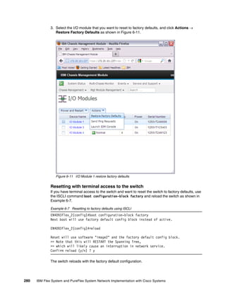


![286 IBM Flex System and PureFlex System Network Implementation with Cisco Systems
Port type ["DATA"/"MGT"/"EXTM"]: MGT
Address or name of remote host: 172.25.101.237
Source file name: 7310boot.img
boot kernel currently contains Software Version 7.2.2.2
New download will replace boot kernel with file "7310boot.img"
from FTP/TFTP server 172.25.101.237.
Connecting via MGT port.
Confirm download operation (y/n) ? y
Starting download...
File appears valid
Download in progress
........................................................................
........................................................................
........................................................................
........................................................................
........
Boot image (FS, 7577851 bytes) download complete.
Writing to flash...This can take up to 90 seconds. Please wait
FS Sector now contains Software Version 7.3.1
Boot image (Kernel, 7577851 bytes) download complete.
Writing to flash...This can take up to 90 seconds. Please wait
Kernel Sector now contains Software Version 7.3.1
Boot image (DFT, 7577851 bytes) download complete.
Writing to flash...This can take up to 90 seconds. Please wait
DFT Sector now contains Software Version 7.3.1
Boot image (Boot, 7577851 bytes) download complete.
Writing to flash...This can take up to 90 seconds. Please wait
Boot Sector now contains Software Version 7.3.1
5. Download the OS image file into image2 and set switch to boot from image2 with the
command copy tftp image2 as displayed in Example 6-17.
Example 6-17 Downloading the OS image file
EN4093flex_2#copy tftp image2
Port type ["DATA"/"MGT"/"EXTM"]: MGT
Address or name of remote host: 172.25.101.237
Source file name: 7310os.img
image2 currently contains Software Version 7.2.2.2
that was downloaded at 6:57:31 Mon Jun 18, 2012.
New download will replace image2 with file "7310os.img"
from FTP/TFTP server 172.25.101.237.
Connecting via MGT port.
Confirm download operation (y/n) ? y
Starting download...
File appears valid
Download in progress
........................................................................
........................................................................
........................................................................
........................................................................
........................................................................](https://image.slidesharecdn.com/ibmflexsystemandpureflexsystemnetworkimplementationwithciscosystems-140711170754-phpapp01/85/Ibm-flex-system-and-pure-flex-system-network-implementation-with-cisco-systems-300-320.jpg)
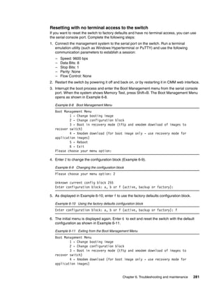
![Chapter 6. Troubleshooting and maintenance 287
.................................................
Image download complete (10484205 bytes)
Writing to flash...This takes about 10 seconds. Please wait
Write complete (10484205 bytes), now verifying FLASH...
Verification of new image2 in FLASH successful.
image2 now contains Software Version 7.3.1
Switch is currently set to boot software image1.
Do you want to change that to the new image2? [y/n]
Oct 1 14:55:05 EN4093flex_2 INFO mgmt: image2 downloaded from host
172.25.101.237, file '7310os.img', software version 7.3.1
y
Next boot will use new software image2.
6. Reboot the switch to activate the new code as shown in Example 6-18.
Example 6-18 Reboot the switch
EN4093flex_2#reload
Reset will use software "image2" and the active config block.
>> Note that this will RESTART the Spanning Tree,
>> which will likely cause an interruption in network service.
Confirm reload (y/n) ? y
7. When the switch reloads, use command show boot to verify that the new firmware 7.3.1.0
is installed and running as shown in Example 6-19.
Example 6-19 New firmware verification
EN4093flex_2#show boot
Currently set to boot software image2, active config block.
NetBoot: disabled, NetBoot tftp server: , NetBoot cfgfile:
Current CLI mode set to IBMNOS-CLI with selectable prompt enabled.
Current FLASH software:
image1: version 7.2.2.2, downloaded 14:55:26 Mon Jun 18, 2012
image2: version 7.3.1, downloaded 22:55:05 Mon Oct 1, 2012
boot kernel: version 7.3.1
Currently scheduled reboot time: none
6.3.3 Recovering from a failed firmware upgrade
Although it is unlikely, the firmware upgrade process might fail. If this situation occurs, you can
still recover the EN4093 switch. To do so, complete the following steps:
1. Connect a PC running a terminal emulation utility to the serial port of your switch while the
switch is off. Then, access the switch as described in the User’s Guide. Use the following
communication parameters to establish terminal emulation session:
– Speed: 9600 bps
– Data Bits: 8
– Stop Bits: 1
– Parity: None
– Flow Control: None](https://image.slidesharecdn.com/ibmflexsystemandpureflexsystemnetworkimplementationwithciscosystems-140711170754-phpapp01/85/Ibm-flex-system-and-pure-flex-system-network-implementation-with-cisco-systems-301-320.jpg)
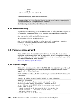
![Chapter 6. Troubleshooting and maintenance 289
Erased 1 sectors
Writing to Flash...9....8....7....6....5....4....3....2....1....done
Protected 1 sectors
**** BOOT CODE ****
Un-Protected 4 sectors
Erasing Flash...
.... done
Erased 4 sectors
Writing to Flash...9....8....7....6....5....4....3....2....1....done
Protected 4 sectors
6. When this process is finished, you are prompted to reconfigure your terminal to 9600 bps
speed:
Change the baud rate back to 9600 bps, hit the <ESC> key
Change the speed of your serial connection, and then press Esc.
7. The Boot Management Menu opens again. Select option 3 now, and change the speed to
115000 bps when the following message appears to start pushing the OS image.
## Switch baudrate to 115200 bps and press ENTER ...
When speed is changed to 115200 bps, press Enter to continue download.
8. Select the OS image that you want to upload to the switch. The Xmodem client starts
sending the image to the switch. When the upload is complete, you see a panel similar to
the one in Example 6-22.
Example 6-22 OS image upgrade
xyzModem - CRC mode, 27186(SOH)/0(STX)/0(CAN) packets, 6 retries
Extracting images ... Do *NOT* power cycle the switch.
**** Switch OS ****
Please choose the Switch OS Image to upgrade [1|2|n] :
9. You are prompted to the select the image space in the switch you want to upgrade. After
you select the OS image bank, you see a panel similar to the one in Example 6-23.
Example 6-23 Upgrading the OS image
Switch OS Image 1 ...
Un-Protected 27 sectors
Erasing Flash.............................. done
Writing to Flash..............................done
Protected 27 sectors
10.When this process is done, you are prompted to reconfigure your terminal to 9600 bps
speed again:
Change the baud rate back to 9600 bps, hit the <ESC> key
Press Esc to show the Boot Management Menu, and choose option 6 to exit and boot the
new image.](https://image.slidesharecdn.com/ibmflexsystemandpureflexsystemnetworkimplementationwithciscosystems-140711170754-phpapp01/85/Ibm-flex-system-and-pure-flex-system-network-implementation-with-cisco-systems-303-320.jpg)
![Chapter 6. Troubleshooting and maintenance 291
Information logged
You can selectively choose what information is logged by Syslog. You have a number of
options:
all All
bgp BGP
cfg Configuration
cli Command-line interface
console Console
dcbx DCB Capability Exchange
difftrak Configuration difference tracking
failover Failover
fcoe Fibre Channel over Ethernet
hotlinks Hot Links
ip Internet protocol
ipv6 IPv6
lacp Link Aggregation Control Protocol
link System port link
lldp LLDP
management Management
mld MLD
netconf NETCONF Configuration Protocol
ntp Network time protocol
ospf OSPF
ospfv3 OSPFv3
rmon Remote monitoring
server Syslog server
spanning-tree-group Spanning Tree Group
ssh Secure Shell
system System
vlag Virtual Link Aggregation
vlan VLAN
vm Virtual machine
vnic VNIC
vrrp Virtual Router Redundancy Protocol
web Web
Use the following ISCLI command syntax:
[no] logging log [<feature>]
For example, the following command enables syslog messages generation for SSH:
logging log ssh
The following command disables syslog messages generation for LACP:
no logging log lacp
The following command displays a list of features for which syslog messages are generated:
show logging
Logging destinations
You can set up to two destinations for reporting. A destination of 0.0.0.0 means logs are
stored locally on the switch. Another instance of a log destination host can be a remote
logging server. In this case, the logs are sent to the server through Syslog. For each of the](https://image.slidesharecdn.com/ibmflexsystemandpureflexsystemnetworkimplementationwithciscosystems-140711170754-phpapp01/85/Ibm-flex-system-and-pure-flex-system-network-implementation-with-cisco-systems-305-320.jpg)


![From Curiosity to ROI — Cost-Benefit Analysis of Agentic Automation [3/6]](https://cdn.slidesharecdn.com/ss_thumbnails/session-3-250903141006-a3917e1a-thumbnail.jpg?width=560&fit=bounds)


