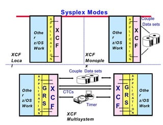
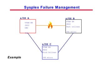
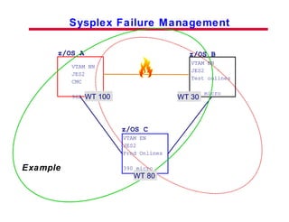
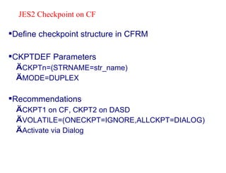
Parallel Sysplex Implementation Parallel Sysplex Center Poughkeepsie, NY USA
Trademarks The following terms used in this presentation are trademarks of the IBM Corporation ACF/VTAM CICS/ESA DB2 DFSMS/z/OS ESA/390 ESCON ES/9000 IBM z/OS/ESA SP PR/SM PS/2 RACF S/390 SYSPLEX TIMER VM/ESA VTAM
Overview Pre-Sysplex Multisystem Applications z/OS Parallel Sysplex Components/Terminolgy Multisystem Sysplex Requirements IBM 9037 Sysplex Timer XCF Signalling Requirements XCF Sysplex Couple Data Sets GRS in a Sysplex Parallel Sysplex Resource Managers Policies Agenda
Parallel Sysplex Implementation Steps Summary Parallel Sysplex Extensions z/OS Logger Automatic Restart Manager (ARM) Sysplex Failure Manager (SFM)  Agenda (cont.)
Pre-Sysplex Multisystem Applications CICS IMS JES2 VTAM GRS JES3 CONSOLES JES2 IMS CICS VTAM GRS JES3 CONSOLES CTC CTC CTC MCS MCS JES3 MVS MCS MVS
z/OS Parallel Sysplex Multiple systems coupled together by hardware and software services that can be  viewed as a single entity. Improves: Availability Systems Management Growth 12 1 2 3 4 5 6 7 8 9 10 11 Coupling Technology Shared data Sysplex Timer ESCON/FICON 9672 zSeries
S/390 Sysplex Components/Terminology Sysplex A set of 1-32 z/OS systems coupled together using hardware and software elements. XCF Cross-system Coupling Facility-provides the z/OS  communications services within a Sysplex. Multisystem Application An authorized application that has functions distributed across more than one z/OS system. CTC Channel to Channel connection-direct connection between two z/OS systems (ESCON CTC, 3088). Sysplex Couple Data Set A data set shared by all XCF components in a sysplex. Contains XCF-related data for the sysplex. Sysplex Timer IBM 9037 Sysplex Timer-external clock used to synchronize the TOD clocks of the systems. Member A specific function of a multisystem application that is defined to XCF and assigned to a group. Group A collection of related members. Serialization The function provided by GRS that is used to serialize resources used by XCF and other users.
S/390 Parallel Sysplex Components/Terminology Parallel Sysplex 2 or more z/OS images in a Sysplex using the coupling facility to share data (up to 32) XES Cross-system Extended Services-provides the z/OS communication services to the coupling facility Coupling Facility Hardware element that provides high-speed caching, list processing, and locking functions Coupling Facility Link/Channel High bandwidth fiber optic link that provides high speed connectivity required for data sharing between the CF and attached CPCs Structures Dynamically partitioned areas of storage within a coupling facility manipulated by z/OS/ESA system services Data Sharing  The ability of concurrent subsystem programs to directly access and change data with integrity. Data Sharing Group Collection of two or more subsystems that access and share data in the coupling facility
Role of the CF LOCKS DATA BUFFERS DATABASE MANAGER DATA BUFFERS DATABASE MANAGER z/OS Sysplex Services Coupling Technology REQUESTS REQUESTS z/OS S/390 z/OS S/390 Locks Lists Caches LOCKS Multi-System Serialization Changed Data
Multisystem Parallel Sysplex Requirements Requirements for all systems in an z/OS Sysplex: Be connected to a common time source Use the same Couple Data Sets Be in the same GRS configuration Have full connectivity to every other system in the Sysplex Have unique system names within the Sysplex Specify the same Sysplex name Have connectivity to all CFs
IBM 9037 Sysplex Timer S0000 Main Menu Time Help Ports Profile Log Maint 01/09/90 09:17:23 UTC Status changed. View log for details. F1=Help 9037 Sysplex Timer Unit (TOD) Clock Management using ETR Synchronization Mode TOD values kept in synchronization with the Sysplex Timer No operator intervention required to set TOD clocks Expanded availability configuration is strongly recommended
Sysplex Modes X C F A P P L I C A T I O N X C F A P P L I C A T I O N XCF Local XCF Monoplex X C F CTCs Couple  Data sets Timer G R S A P P L I C A T I O N X C F G R S A P P L I C A T I O N XCF Multisystem Other z/OS Work Other z/OS Work Other z/OS Work Other z/OS Work Couple Data sets
XCF-Multisystem Sysplex Configurations X C F X C F G R S G R S A P P L A P P L Multiple Physical Processors X C F X C F G R S G R S A P P L A P P L Multiple LPARs on a Single Processor X C F X C F G R S G R S A P P L A P P L Multiple VM Guests * * * Note: Sysplex Timer and CTC considerations Processor 1 Processor 2 z/OS 1 z/OS 1 z/OS 2 z/OS 2
Full Connectivity to all systems is required Redundant configurations are recommended Potential configurations include: ESCON Channels operating in CTC mode ( Point-to-Point ) Channels supporting CTC communications must be paired; one operating in CTC ( Type=CTC )  mode and the other operating in native mode ( Type=CNC ) ESCON Channels with ESCON Directors ( ESCD ) Reduces the number of CTCs that must be used Allows the native ESCON channels to be used for attaching other ESCON devices PR/SM LPARs with ESCON Multiple Image Facility Using shared channels further reduces channel requirements Signalling structures z/OS Sysplex Connectivity
XCF CTC Signalling Requirements Outbound Inbound Inbound Outbound System  A System  B Connecting Link At least one connecting link must be defined between each system in the Sysplex -  A connecting link consists of a pair of inbound-outbound  signalling paths between systems -  Signalling paths are uni-directional -  Recommended minimum is 4 signalling paths between each  system (2 inbound and 2 outbound)  XCF Logical connections:
XCF CTC Signalling Requirements . . Outbound Inbound Inbound Outbound Connecting Link XCF Logical connections: ESCON CTC Physical connections 600 100 601 101 SYS1 SYS2 X C F X C F PATHOUT (600) PATHIN (601) PATHIN (100) PATHOUT (101) SYS1  SYS2  ctc  cnc  System 1  System 2  CHPID 03  CHPID 22  System 1 I/O Definition System 1  System 2  CHPID PATH=((03)),TYPE=CTC CNTLUNIT CUNUMBR=600,PATH=((03)), UNITADD=(00,2)),UNIT=SCTC IODEVICE  ADDRESS=(600,2),CUNUMBR=(600), UNIT=SCTC System 2 I/O Definition CHPID PATH=(22)),TYPE=CNC CNTLUNIT CUNUMBR=100,PATH=((22)), UNITADD=(00,2)),UNIT=SCTC IODEVICE  ADDRESS=(100,2),CUNUMBR=(100), UNIT=SCTC
XES signalling provides the ability to establish XCF signalling connectivity through the coupling facility In addition to, or instead of, the existing signalling capability using CTC links XES automatically configures paths to all systems using a common CF list structure Defining a coupling facility list structure as an outbound definition for XCF will cause an XCF signalling path to be established with every other system that has the structure defined as an inbound path A coupling facility list structure can be defined and be used for both outbound and inbound XCF signalling paths XES Signalling Structures
Installation Unidirectional, point-to-point; Minimum CTC paths to provide full connectivity for 8 system Sysplex is 56 (8*(8-1)); 112 for redundancy Bidirectional, one-to-many; one coupling facility list structure can support more than an 8 system Sysplex;  2 for redundancy Administration PARMLIB, I/O Definition, Shared COUPLExx member not practical because of CTC addresses PARMLIB, Administrative policy, shared COUPLExx member possible if all systems share the same list structure(s) and all other XCF parameters are the same Recovery Manual XES and Coupling Facility initiated XCF CTC XES Signalling XES Signalling XES Signalling XCF CTC XCF CTC XCF CTC Signalling versus XES Signalling
COUPLE  SYSPLEX (PLXM) PCOUPLE (SYS1.XCF#PLXM.CDS01) ACOUPLE (SYS1.XCF#PLXM.CDS02) PATHIN  STRNAME(IXCSTR1) PATHOUT  STRNAME(IXCSTR2)  Signalling Definitions Coupling Facility CTC COUPLE  SYSPLEX (PLXM) PCOUPLE (SYS1.XCF#PLXM.CDS01) ACOUPLE (SYS1.XCF#PLXM.CDS02) PATHIN  DEVICE(E40,E41) PATHIN  DEVICE(890,891) PATHOUT  DEVICE(100,101) PATHOUT  DEVICE(200,201)
XCF Sysplex Couple Data Set Required for XCF-Monoplex or XCF-Multisystem Sysplex modes An alternate couple data set may be specified Couple data set(s) must be shared by all systems in the Sysplex Some information kept in the couple data set includes: Names of the systems in the Sysplex Status of the systems in the Sysplex A system status field that is periodically updated by each system to indicate its "health" Names of groups and members Member status for members using permanent status recording All systems in the Sysplex will go in wait state,  if couple data set(s) are not usable Defined in PARMLIB; May be added or removed using SETXCF Shared data repository for the systems in a Sysplex
XCF Sysplex Couple Data Set . . . Avoid placing Couple Data set on volume with high use data sets Avoid a volume that has the RESERVE macro issued against it Normal I/O activity - Status Updates - 2 I/Os every 3 seconds per system in Sysplex Additional I/O activity I/O to the Couple Data Set for every action message in Sysplex (for example, WTOR) Modifications to the Sysplex (for example, activation of a new group) During recovery
GRS Multisystem (Global) serialization is required for XCF-Multisystem Sysplex mode In a multisystem Sysplex GRS can use lock structure to manage GRS configuration.  Benefits: Improved Performance All systems in the Sysplex must be in the same GRS configuration Global Resource Serialization in a Sysplex z/OS z/OS RSA RNLs RNLs CTC G R S G R S X C F X C F
z/OS Parallel Sysplex Resource Manager Policies Sysplex-wide administrative policies Automated, system-managed goals Changes communicated to all systems in the sysplex Dynamically changed using commands IPL not required z/OS Coupling Facility Resource Manager (CFRM) Policy z/OS Sysplex Failure Mangement (SFM) Policy z/OS Workload Manager (WLM) Policy z/OS Automatic Restart Manager (ARM) Policy z/OS Logger Inventory
Parallel Sysplex Implementation Steps
Planning for a z/OS Parallel Sysplex Review: Sysplex Implementation Requirements z/OS Sysplex and S/390 Parallel Sysplex Software/Hardware Network Considerations Potential Applications Operations Changes Testing Requirements
Customization Tasks for Parallel Sysplex SYS1.PARMLIB IEASYMxx SYSNAME, SYMDEF definitions IEASYSxx SYSNAME, GRS, GRSCNF, CLOCK, PLEXCFG, CON, COUPLE CLOCKxx GRSCNFxx GRSRNLxx CONSOLxx COUPLExx  SYSPLEX name,  COUPLE data sets, Signalling paths Format Couple data sets IPL with new configuration Bring other systems into the SYSPLEX
IEASYMxx Member of PARMLIB SYSDEF SYSCLONE(&SYSNAME(3:2)) SYSPARM(PS) SYMDEF(&SYSR1='BMRS11') SYMDEF(&SYSR2='&SYSR1(1:5).2') SYMDEF(&GRSPARM=‘STAR’) SYMDEF(&COUPLE=‘PS’) SYSDEF HWNAME(AB02) LPARNAME(Z021) SYSNAME(ZMB0) SYMDEF(&APPN='8B') SYMDEF(&SSCPID='811') SYSDEF HWNAME(AB01) LPARNAME(Z011) SYSNAME(ZMB1)  SYMDEF(&APPN='8C')  SYMDEF(&SSCPID='812')
IEASYSxx Member of PARMLIB PLEXCFG=ANY, GRS=&GRSPARM, GRSRNL=PS, CON=PS, CLOCK=PS, COUPLE=&COUPLE,
CLOCKxx Member of PARMLIB ETRMODE  YES ETRZONE  YES ETRDELTA  10 TIMEZONE  E.08.00.00
GRSRNLxx Member of PARMLIB /*  System EXCLusion List  */ RNLDEF  RNL(EXCL) TYPE(SPECIFIC) QNAME(SYSDSN)  RNAME(SYS1.LOGREC) /*  System INCLusion List  */ RNLDEF  RNL(INCL) TYPE(GENERIC) QNAME(SYSDSN) /*  System CONversion List  */ RNLDEF  RNL(CON) TYPE(PATTERN) QNAME(*) SYSPLEX provides the capability to dynamically change the GRS Resource Name List
Implementing Parallel Sysplex Format SYSPLEX couple data sets Update COUPLExx for signalling paths  Format other couple data sets Coupling Facility Resource Management (CFRM) Sysplex Failure Management  (SFM) Workload Management  (WLM) Automatic Restart Management (ARM)  Define CF structures XCF/XES signalling VTAM  JES2  RACF IRLM LOGGER others......
Sysplex Couple Data Set Required for: XCF-Multisystem and XCF-Monoplex Must be shared by  ALL  systems in sysplex Avoid placing on busy volumes Define primary and alternate  Alternate is optional but recommended Defined by IXCL1DSU batch utility IXCSYSPF in SYS1.SAMPLIB  Control Statement: DEFINEDS DSN(SYS1.XCF#PLXM.CDS01) VOLSER(BMCD01) SYSPLEX(PLXM) MAXSYSTEM(6) CATALOG DATA TYPE(SYSPLEX) ITEM NAME(GROUP)  NUMBER(20) ITEM NAME(MEMBER)  NUMBER(50)
COUPLE  SYSPLEX (PLXM) PCOUPLE (SYS1.XCF#PLXM.CDS01) ACOUPLE (SYS1.XCF#PLXM.CDS02) PATHIN  STRNAME(IXCSTR1) PATHIN  DEVICE(E40,E41) PATHIN  DEVICE(890,891) ...  ... PATHOUT  STRNAME(IXCSTR1) PATHOUT  DEVICE(100,101) PATHOUT  DEVICE(200,201) ... ... Signalling Definitions - COUPLExx Coupling Facility CTCs
Coupling Facility Resource Manager Policy Coupling Facility Resource Manager (CFRM) policy Defines Coupling Facilities (CFs) to be used Type of Coupling Facility CPCID Sequence Number etc..... Defines structures and their placement in the CFs Preference List,  Exclusion List Batch Administrative Utility
Define CFRM Couple Data Set IXCCFRMF member in SYS1.SAMPLIB Execute IXCL1DSU batch utility  Alternate CFRM couple data set is HIGHLY recommended Control Statements: DEFINEDS  SYSPLEX(PLXM) DSN(SYS1.CFR#PLXM.CDS01) VOLSER(BMCD02) CATALOG DATA  TYPE (CFRM) ITEM  NAME(POLICY)  NUMBER(6) ITEM  NAME(CF)  NUMBER(5) ITEM  NAME(STR)  NUMBER(20) ITEM  NAME(CONNECT)  NUMBER(32)
Define CFRM Policy IXCCFRMP member in SYS1.SAMPLIB Execute IXCMAIPU administrative data utility  CFRM couple data set must be pre-formatted IXCMAIPU administrative data utility is used to add update,  or delete policy data  Structure sizes must be estimated CFSizer  has recommendations RACF protect IXCMAIPU Resource name  ‘MVSADMIN.XCF.CFRM' in FACILITY class
DATA TYPE(CFRM)  REPORT(YES)  DEFINE POLICY NAME(PLXM)  REPLACE(YES) CF  NAME(C033) TYPE(002064) MFG(IBM) PARTITION(3) SEQUENCE(000000019B1A) CPCID(00)   CF  NAME(C021) TYPE(002064) ... ... STRUCTURE  NAME(IXCPATH1) SIZE(16316)  PREFLIST(C033,C021)  REBUILDPERCENT(1) STRUCTURE  NAME(ISTGENERIC) SIZE(10000)  PREFLIST(C033,C021) STRUCTURE  NAME(ISTMNPS) SIZE(12288)  PREFLIST(C021,C033) STRUCTURE  NAME(IXCPATH2) SIZE(16316)  PREFLIST(C021,C033) EXCLLIST(IXCSTR1)  CFRM Policy Control Statements Example: C033 C021 IIXCPATH1 ISTGENERIC ISTMNPS IXCPATH2
Activating CFRM Policy Make CFRM Couple Data Set available to z/OS: SETXCF COUPLE,PCOUPLE=SYS1.CFR#PLXM.CDS01,TYPE=CFRM SETXCF COUPLE,ACOUPLE=SYS1.CFR#PLXM.CDS02,TYPE=CFRM Activate CFRM Policy: SETXCF START,POLICY,POLNAME=PLXM,TYPE=CFRM Only one member of the sysplex needs to activate the policy
Update COUPLExx Member of PARMLIB COUPLE  SYSPLEX(&SYSPLEX) PCOUPLE(SYS1.XCF#&SYSPLEX..CDS01) ACOUPLE(SYS1.XCF#&SYSPLEX..CDS02) DATA  TYPE(CFRM) PCOUPLE(SYS1.CFR#&SYSPLEX..CSD01) ACOUPLE(SYS1.CFR#&SYSPLEX..CDS02)  PATHOUT  STRNAME(IXCSTR1)  PATHIN  STRNAME(IXCSTR2)
z/OS Workload Manager Policy z/OS Workload Manager (WLM) Policy Performance goals Not parameter driven Replaces SRM IPS & ICS Business importance ISPF Dialogs to define
Define WLM Couple Data Sets IWMFTCDS member in SYS1.SAMPLIB Execute IXCL1DSU batch utility  Alternate WLM couple data set is strongly recommended Define resource name  MVSADMIN.WLM.POLICY  in the FACILITY class of RACF Use PERMIT to allow access Control Statements: DEFINEDS  SYSPLEX(PLXM) DSN(SYS1.WLM#PLXM.CDS01) VOLSER(BMCD01) CATALOG DATA  TYPE  (WLM) ITEM  NAME(POLICY)  NUMBER(6) ITEM  NAME(WORKLOAD)  NUMBER(35) ITEM  NAME(SRVCLASS)  NUMBER(100)
Activating WLM Policy Make WLM Couple Data Set available to z/OS: SETXCF COUPLE,PCOUPLE=SYS1.WLM#PLXM.CDS01,TYPE=WLM SETXCF COUPLE,ACOUPLE=SYS1.WLM#PLXM.CDS02,TYPE=WLM Activate WLM Service Policy: VARY WLM,POLICY=wlm_policy_name Don't forget to update COUPLExx member
Sysplex Failure Management Policy Sysplex Failure Mangement (SFM) policy Automates Sysplex recovery actions: Loss of connectivity System status update missing Storage Reconfiguration Batch Administrative Utility
Sysplex Failure Management z/OS A VTAM NN JES2 CMC 962 Example z/OS B VTAM EN JES2 Test onlines 390 micro VTAM EN JES2  Prod Onlines 390 micro z/OS C
Sysplex Failure Management z/OS A VTAM NN JES2 CMC 962 Example z/OS B VTAM EN JES2 Test onlines 390 micro VTAM EN JES2  Prod Onlines 390 micro z/OS C WT 100 WT 30 WT 80
Define SFM Couple Data Set IXCSFMF member in SYS1.SAMPLIB Execute IXCL1DSU batch utility  Alternate SFM couple data set is recommended Control Statements: DEFINEDS  SYSPLEX(PLXM)  DSN(SYS1.SFM#PLXM.CDS01) VOLSER(BMCD01) CATALOG DATA  TYPE (SFM) ITEM  NAME(POLICY)  NUMBER(6) ITEM  NAME(SYSTEM)  NUMBER(8) ITEM  NAME(RECONFIG)  NUMBER(4)
Define Sysplex Failure Management Policy IXCSFMP member in SYS1.SAMPLIB Execute IXCMAIPU administrative data utility  SFM couple data set must be pre-formatted IXCMAIPU administrative data utility is used to add update,  or delete policy data  RACF protect IXCMAIPU Resource name  ‘MVSADMIN.XCF.SFM' in FACILITY class
DATA TYPE(SFM) REPORT(YES)  DEFINE POLICY NAME(NORMAL)  CONNFAIL(YES) REPLACE(YES) SYSTEM NAME(*)    WEIGHT(1)  ISOLATETIME(0)   SYSTEM NAME(ZMB0) WEIGHT(40)  SYSTEM NAME(ZMB1) WEIGHT(40)  SYSTEM NAME(ZMB3)  WEIGHT(10)  RECONFIG  FAILSYS(SYSC) ACTSYS(SYSD) TARGETSYS(ALL)  ESTORE(YES) STORE(YES) SFM Policy Control Statements Example:
Activating SFM Policy Make SFM Couple Data Set available to z/OS: SETXCF COUPLE,PCOUPLE=SYS1.SFM#PLXM.CDS01,TYPE=SFM SETXCF COUPLE,ACOUPLE=SYS1.SFM#PLXM.CDS02,TYPE=SFM Activate SFM Policy: SETXCF START,POLICY,POLNAME=NORMAL,TYPE=SFM Only one member of the sysplex needs to activate the policy Update COUPLExx member
CDS Types: Sysplex Couple Data Set CFRM SFM  Separate/Combined WLM Allocation: Space requirements Primary/Alternate Format:  IXCL1DSU (All) ADMIN:  IXCMIAPU (CFRM,SFM) ISPF Interface (WLM) Sysplex Implementation Summary Sysplex Implementation Activities IEASYSxx: PLEXCFG GRS  GRSCNF  GRSCNFxx GRSRNL  GRSRNLxx CLOCK  CLOCKxx CONSOLE  CONSOLxx CNGRPxx COUPLE  COUPLExx  CSS Configuration OS Configuration IOCDS Security Profiles CBD.CPC.IOCDS CBD.CPC.IPLPARM IPLPARM HMC  Setup Profiles  SYSPLEX  Name Network Name (S/390 T/R) Processor Id names (HCD) CPC Names CF Names Structures Consoles JES2 Checkpoint Signalling Paths z/OS System Names HW/SW Requirements HCD PARMLIB Planning COUPLE
Define checkpoint structure in CFRM CKPTDEF Parameters CKPTn=(STRNAME=str_name) MODE=DUPLEX Recommendations CKPT1 on CF, CKPT2 on DASD VOLATILE=(ONECKPT=IGNORE,ALLCKPT=DIALOG) Activate via Dialog JES2 Checkpoint on CF
z/OS System Logger A P P L 2 L O G G E R A P P L 1 z/OSA Log Data Set Log Data Set A P P L 2 L O G G E R A P P L 1 z/OSB List structure logstream 1 List structure logstream 2 Coupling Facility Sysplex-Wide Offload  Process Offload  Process
CICS Tran. Server for z/OS IMS/ESA 6.1 Shared Queues Operlog Logrec APPC/MVS z/OS Resource Recovery Services Websphere TVS ... Users of System Logger: LOG WTR A z/OS_A I X G L O G R LOG WTR B CF_1 LOG WTR A z/OS_B LOG WTR B I X G L O G R System Logger Users
System Logger Recommendations Logstream/Structure Recommendations: Aim for 10-20 logstreams per structure.  During recovery, each z/OS will maximize parallelism ACROSS structures, but serially within a single structure.  Remember (current) overall limit of 255 structures. Try to have at least 2 active logstreams per CF structure, connected to more than one system, to allow peer recovery in case of failure. Try to put logstreams with similar storage requirements in same structure - storage is split evenly between all logstreams, so CF storage will be wasted if logstreams have vastly different usage patterns. When another logstream is connected, the existing logstreams will be re-sized.  This could potentially cause short term logstream-full conditions and impact exploiters.
Logstream/Structure Recommendations: AVGBUFSIZE & MAXBUFSIZE are specified at structure level, so try to ensure all logstreams in a structure have similar block size characteristics. Use a realistic number for LOGSNUM - every POTENTIAL logstream takes up some storage in the structure. Do not oversize the logstream structures - every logstream is potentially duplexed in a data space - so very large logstreams can lead to processor storage constraint.  Also, very large logstreams mean long offloads which can impact logger performance.  More frequent small offloads are better than a few large ones.  One offload every 5-10 minutes would be an ideal balance. System Logger Recommendations  cont...
Offload Dataset Recommendations: Use a CISZ of 24576 for offload datasets.  Staging datasets MUST have a CISZ of 4096 or writes to them will fail. Make the offload datasets as large as  reasonable , to reduce overhead of allocating additional datasets in the middle of an offload.  Bear in mind retpd and age of data in each offload dataset.  RETPD and AUTODELETE to control deletion of data from logstream and deletion of log data sets. Ensure data sets are defined with SHROPTIONS(3,3) System Logger Recommendations  cont...
Recommendations: For OLTP workloads, use HIGHOFFLOAD of 80% and LOWOFFLOAD of 60% as a starting point.  Check the documentation for the connector (CICS or whatever) for specific recommendations, and monitor SMF Type 88 records using IXGRPT1 provided in SAMPLIB.  Do not set HIGHOFFLOAD higher than 80%, in case spurts of activity would fill the log stream before OFFLOAD can provide additional space. Do not set HIGHOFFLOAD so high that you rarely get offloads - log stream and offload data sets only get cleaned up when offload is invoked. Make sure you have sufficient auxiliary storage to back the logger data spaces. IXGRPT1 provides counts of number of offloads, number of structure full and entry full, and avg buffer size, amongst other things.  See SMF manual, macro IXGSMF88 in SYS1.MACLIB, and member IXGRPT1 in SYS1.SAMPLIB for a description of all the fields. System Logger Recommendations  cont...
Offload devices should be fast enough to offload difference between HIGHOFFLOAD and LOWOFFLOAD faster than space above HIGHOFFLOAD fills up. System Logger Review
Format Logger Inventory Format the z/OS Logger Inventory Couple Data Set with: LSR –  number of structures LSTRR –  number of log streams //STEP1  EXEC PGM=IXCL1DSU //SYSPRINT DD * //SYSIN  DD * DEFINEDS SYSPLEX(PLXM) DSN(SYS1.LGR#PLXM.CDS01) VOLSER(BMCD03) CATALOG DATA TYPE(LOGR) ITEM NAME(LSR) NUMBER(5) ITEM NAME(LSTRR) NUMBER(10)
Define Log Streams Associate data sets, log stream names, structure names and attributes. Structures may be defined or deleted  Streams may be defined, deleted or updated  //STEP1  EXEC PGM=IXCMIAPU //SYSIN  DD * DATA TYPE(LOGR) REPORT(YES) DEFINE STRUCTURE NAME(LOGGER_OPERLOG) AVGBUFSIZE(512) MAXBUFSIZE(4096)   LOGSNUM(5) DEFINE LOGSTREAM NAME(SYSPLEX_OPERLOG) STRUCTNAME(LOGGER_OPERLOG) ...
Update the CFRM Policy Update CFRM policy with names of the structures to be used by z/OS System Logger. //STEP1  EXEC PGM=IXCMIAPU //SYSIN  DD * DATA TYPE(CFRM) REPORT(YES) . . . DEFINE STR(LOGGER_OPERLOG) SIZE(13568) PREFLIST(C033,C021)
Automatic Restart Manager  The  Automatic Restart Manager (ARM)  is an z/OS recovery function Improves the availability of specified subsystems and applications Automatically restarting them as requested Function of the Cross-System Coupling Facility (XCF) component  Runs in XCF address space  Uses data spaces Augments the functions of production controllers, automation products, and job schedulers Subsystems that use ARM are expected to perform their own transaction level and database recovery Requires: ARM Couple data sets which have connectivity to all the systems on which ARM is active
ARM Environment XCF XCF ARM ARM ARM Couple Data Set Started Tasks/ Batch Started Tasks/ Batch Coupling Facility SYSA SYSB z/OS z/OS
ARM Restart Inplace CF SYSA SYSB RTM Error Application Automatic Restart Manager EOM Resource Manager - Invoke Exits - Determine if Element is restartable - Execute appropriate Restart Method Restart on SYSA Executing on SYSA
ARM Restart on other Systems ARM SYSA SYSB SYSC GRP01 Appl1 Appl2 Appl3 GRP02 Appl4 Appl5 ARM Policy Couple Data Set CF GRP01 Appl1 Appl2 Appl3 GRP02 Appl4 Appl5 SYSB leaves Sysplex XCF Address Space Applications discontinue on SYSB Restart on SYSA Restart on SYSC XCF Status update missing
ARM Couple Data Sets Primary ARM Couple Data Set Alternate ARM Couple Data Set Couple Data Set Format Utility . . DEFINEDS SYSPLEX(PLXM)  DSN(SYS1.ARM#PLXM.CDS01)  VOLSER(BMCD01)  DATA TYPE(ARM)  ITEM NAME(POLICY)  NUMBER(3) ITEM NAME(MAXELEM)  NUMBER(10)  ITEM NAME(TOTELEM)  NUMBER(500)
ARM Policy - IXCMIAPU //IXCARMP0  JOB //STEP1  EXEC PGM=IXCMIAPU //SYSPRINT  DD SYSOUT=A //SYSIN  DD * DATA TYPE(ARM)  DEFINE POLICY NAME(ARMPLXM1) RESTART_GROUP(DEFAULT) TARGET_SYSTEM(*) ELEMENT(*)  RESTART_ATTEMPTS(0) RESTART_GROUP(VTAMGRP) TARGER_SYSTEM(*) ELEMENT(NET@V*) RESTART_ATTEMPTS(3,300)  READY_TIMEOUT(900) TERMTYPE(ELEMTERM) /* IXCMIAPU Utility example

Parallel Sysplex Implement2

  • 1.
    Parallel Sysplex ImplementationParallel Sysplex Center Poughkeepsie, NY USA
  • 2.
    Trademarks The followingterms used in this presentation are trademarks of the IBM Corporation ACF/VTAM CICS/ESA DB2 DFSMS/z/OS ESA/390 ESCON ES/9000 IBM z/OS/ESA SP PR/SM PS/2 RACF S/390 SYSPLEX TIMER VM/ESA VTAM
  • 3.
    Overview Pre-Sysplex MultisystemApplications z/OS Parallel Sysplex Components/Terminolgy Multisystem Sysplex Requirements IBM 9037 Sysplex Timer XCF Signalling Requirements XCF Sysplex Couple Data Sets GRS in a Sysplex Parallel Sysplex Resource Managers Policies Agenda
  • 4.
    Parallel Sysplex ImplementationSteps Summary Parallel Sysplex Extensions z/OS Logger Automatic Restart Manager (ARM) Sysplex Failure Manager (SFM) Agenda (cont.)
  • 5.
    Pre-Sysplex Multisystem ApplicationsCICS IMS JES2 VTAM GRS JES3 CONSOLES JES2 IMS CICS VTAM GRS JES3 CONSOLES CTC CTC CTC MCS MCS JES3 MVS MCS MVS
  • 6.
    z/OS Parallel SysplexMultiple systems coupled together by hardware and software services that can be viewed as a single entity. Improves: Availability Systems Management Growth 12 1 2 3 4 5 6 7 8 9 10 11 Coupling Technology Shared data Sysplex Timer ESCON/FICON 9672 zSeries
  • 7.
    S/390 Sysplex Components/TerminologySysplex A set of 1-32 z/OS systems coupled together using hardware and software elements. XCF Cross-system Coupling Facility-provides the z/OS communications services within a Sysplex. Multisystem Application An authorized application that has functions distributed across more than one z/OS system. CTC Channel to Channel connection-direct connection between two z/OS systems (ESCON CTC, 3088). Sysplex Couple Data Set A data set shared by all XCF components in a sysplex. Contains XCF-related data for the sysplex. Sysplex Timer IBM 9037 Sysplex Timer-external clock used to synchronize the TOD clocks of the systems. Member A specific function of a multisystem application that is defined to XCF and assigned to a group. Group A collection of related members. Serialization The function provided by GRS that is used to serialize resources used by XCF and other users.
  • 8.
    S/390 Parallel SysplexComponents/Terminology Parallel Sysplex 2 or more z/OS images in a Sysplex using the coupling facility to share data (up to 32) XES Cross-system Extended Services-provides the z/OS communication services to the coupling facility Coupling Facility Hardware element that provides high-speed caching, list processing, and locking functions Coupling Facility Link/Channel High bandwidth fiber optic link that provides high speed connectivity required for data sharing between the CF and attached CPCs Structures Dynamically partitioned areas of storage within a coupling facility manipulated by z/OS/ESA system services Data Sharing The ability of concurrent subsystem programs to directly access and change data with integrity. Data Sharing Group Collection of two or more subsystems that access and share data in the coupling facility
  • 9.
    Role of theCF LOCKS DATA BUFFERS DATABASE MANAGER DATA BUFFERS DATABASE MANAGER z/OS Sysplex Services Coupling Technology REQUESTS REQUESTS z/OS S/390 z/OS S/390 Locks Lists Caches LOCKS Multi-System Serialization Changed Data
  • 10.
    Multisystem Parallel SysplexRequirements Requirements for all systems in an z/OS Sysplex: Be connected to a common time source Use the same Couple Data Sets Be in the same GRS configuration Have full connectivity to every other system in the Sysplex Have unique system names within the Sysplex Specify the same Sysplex name Have connectivity to all CFs
  • 11.
    IBM 9037 SysplexTimer S0000 Main Menu Time Help Ports Profile Log Maint 01/09/90 09:17:23 UTC Status changed. View log for details. F1=Help 9037 Sysplex Timer Unit (TOD) Clock Management using ETR Synchronization Mode TOD values kept in synchronization with the Sysplex Timer No operator intervention required to set TOD clocks Expanded availability configuration is strongly recommended
  • 12.
    Sysplex Modes XC F A P P L I C A T I O N X C F A P P L I C A T I O N XCF Local XCF Monoplex X C F CTCs Couple Data sets Timer G R S A P P L I C A T I O N X C F G R S A P P L I C A T I O N XCF Multisystem Other z/OS Work Other z/OS Work Other z/OS Work Other z/OS Work Couple Data sets
  • 13.
    XCF-Multisystem Sysplex ConfigurationsX C F X C F G R S G R S A P P L A P P L Multiple Physical Processors X C F X C F G R S G R S A P P L A P P L Multiple LPARs on a Single Processor X C F X C F G R S G R S A P P L A P P L Multiple VM Guests * * * Note: Sysplex Timer and CTC considerations Processor 1 Processor 2 z/OS 1 z/OS 1 z/OS 2 z/OS 2
  • 14.
    Full Connectivity toall systems is required Redundant configurations are recommended Potential configurations include: ESCON Channels operating in CTC mode ( Point-to-Point ) Channels supporting CTC communications must be paired; one operating in CTC ( Type=CTC ) mode and the other operating in native mode ( Type=CNC ) ESCON Channels with ESCON Directors ( ESCD ) Reduces the number of CTCs that must be used Allows the native ESCON channels to be used for attaching other ESCON devices PR/SM LPARs with ESCON Multiple Image Facility Using shared channels further reduces channel requirements Signalling structures z/OS Sysplex Connectivity
  • 15.
    XCF CTC SignallingRequirements Outbound Inbound Inbound Outbound System A System B Connecting Link At least one connecting link must be defined between each system in the Sysplex - A connecting link consists of a pair of inbound-outbound signalling paths between systems - Signalling paths are uni-directional - Recommended minimum is 4 signalling paths between each system (2 inbound and 2 outbound) XCF Logical connections:
  • 16.
    XCF CTC SignallingRequirements . . Outbound Inbound Inbound Outbound Connecting Link XCF Logical connections: ESCON CTC Physical connections 600 100 601 101 SYS1 SYS2 X C F X C F PATHOUT (600) PATHIN (601) PATHIN (100) PATHOUT (101) SYS1 SYS2 ctc cnc System 1 System 2 CHPID 03 CHPID 22 System 1 I/O Definition System 1 System 2 CHPID PATH=((03)),TYPE=CTC CNTLUNIT CUNUMBR=600,PATH=((03)), UNITADD=(00,2)),UNIT=SCTC IODEVICE ADDRESS=(600,2),CUNUMBR=(600), UNIT=SCTC System 2 I/O Definition CHPID PATH=(22)),TYPE=CNC CNTLUNIT CUNUMBR=100,PATH=((22)), UNITADD=(00,2)),UNIT=SCTC IODEVICE ADDRESS=(100,2),CUNUMBR=(100), UNIT=SCTC
  • 17.
    XES signalling providesthe ability to establish XCF signalling connectivity through the coupling facility In addition to, or instead of, the existing signalling capability using CTC links XES automatically configures paths to all systems using a common CF list structure Defining a coupling facility list structure as an outbound definition for XCF will cause an XCF signalling path to be established with every other system that has the structure defined as an inbound path A coupling facility list structure can be defined and be used for both outbound and inbound XCF signalling paths XES Signalling Structures
  • 18.
    Installation Unidirectional, point-to-point;Minimum CTC paths to provide full connectivity for 8 system Sysplex is 56 (8*(8-1)); 112 for redundancy Bidirectional, one-to-many; one coupling facility list structure can support more than an 8 system Sysplex; 2 for redundancy Administration PARMLIB, I/O Definition, Shared COUPLExx member not practical because of CTC addresses PARMLIB, Administrative policy, shared COUPLExx member possible if all systems share the same list structure(s) and all other XCF parameters are the same Recovery Manual XES and Coupling Facility initiated XCF CTC XES Signalling XES Signalling XES Signalling XCF CTC XCF CTC XCF CTC Signalling versus XES Signalling
  • 19.
    COUPLE SYSPLEX(PLXM) PCOUPLE (SYS1.XCF#PLXM.CDS01) ACOUPLE (SYS1.XCF#PLXM.CDS02) PATHIN STRNAME(IXCSTR1) PATHOUT STRNAME(IXCSTR2) Signalling Definitions Coupling Facility CTC COUPLE SYSPLEX (PLXM) PCOUPLE (SYS1.XCF#PLXM.CDS01) ACOUPLE (SYS1.XCF#PLXM.CDS02) PATHIN DEVICE(E40,E41) PATHIN DEVICE(890,891) PATHOUT DEVICE(100,101) PATHOUT DEVICE(200,201)
  • 20.
    XCF Sysplex CoupleData Set Required for XCF-Monoplex or XCF-Multisystem Sysplex modes An alternate couple data set may be specified Couple data set(s) must be shared by all systems in the Sysplex Some information kept in the couple data set includes: Names of the systems in the Sysplex Status of the systems in the Sysplex A system status field that is periodically updated by each system to indicate its "health" Names of groups and members Member status for members using permanent status recording All systems in the Sysplex will go in wait state, if couple data set(s) are not usable Defined in PARMLIB; May be added or removed using SETXCF Shared data repository for the systems in a Sysplex
  • 21.
    XCF Sysplex CoupleData Set . . . Avoid placing Couple Data set on volume with high use data sets Avoid a volume that has the RESERVE macro issued against it Normal I/O activity - Status Updates - 2 I/Os every 3 seconds per system in Sysplex Additional I/O activity I/O to the Couple Data Set for every action message in Sysplex (for example, WTOR) Modifications to the Sysplex (for example, activation of a new group) During recovery
  • 22.
    GRS Multisystem (Global)serialization is required for XCF-Multisystem Sysplex mode In a multisystem Sysplex GRS can use lock structure to manage GRS configuration. Benefits: Improved Performance All systems in the Sysplex must be in the same GRS configuration Global Resource Serialization in a Sysplex z/OS z/OS RSA RNLs RNLs CTC G R S G R S X C F X C F
  • 23.
    z/OS Parallel SysplexResource Manager Policies Sysplex-wide administrative policies Automated, system-managed goals Changes communicated to all systems in the sysplex Dynamically changed using commands IPL not required z/OS Coupling Facility Resource Manager (CFRM) Policy z/OS Sysplex Failure Mangement (SFM) Policy z/OS Workload Manager (WLM) Policy z/OS Automatic Restart Manager (ARM) Policy z/OS Logger Inventory
  • 24.
  • 25.
    Planning for az/OS Parallel Sysplex Review: Sysplex Implementation Requirements z/OS Sysplex and S/390 Parallel Sysplex Software/Hardware Network Considerations Potential Applications Operations Changes Testing Requirements
  • 26.
    Customization Tasks forParallel Sysplex SYS1.PARMLIB IEASYMxx SYSNAME, SYMDEF definitions IEASYSxx SYSNAME, GRS, GRSCNF, CLOCK, PLEXCFG, CON, COUPLE CLOCKxx GRSCNFxx GRSRNLxx CONSOLxx COUPLExx SYSPLEX name, COUPLE data sets, Signalling paths Format Couple data sets IPL with new configuration Bring other systems into the SYSPLEX
  • 27.
    IEASYMxx Member ofPARMLIB SYSDEF SYSCLONE(&SYSNAME(3:2)) SYSPARM(PS) SYMDEF(&SYSR1='BMRS11') SYMDEF(&SYSR2='&SYSR1(1:5).2') SYMDEF(&GRSPARM=‘STAR’) SYMDEF(&COUPLE=‘PS’) SYSDEF HWNAME(AB02) LPARNAME(Z021) SYSNAME(ZMB0) SYMDEF(&APPN='8B') SYMDEF(&SSCPID='811') SYSDEF HWNAME(AB01) LPARNAME(Z011) SYSNAME(ZMB1) SYMDEF(&APPN='8C') SYMDEF(&SSCPID='812')
  • 28.
    IEASYSxx Member ofPARMLIB PLEXCFG=ANY, GRS=&GRSPARM, GRSRNL=PS, CON=PS, CLOCK=PS, COUPLE=&COUPLE,
  • 29.
    CLOCKxx Member ofPARMLIB ETRMODE YES ETRZONE YES ETRDELTA 10 TIMEZONE E.08.00.00
  • 30.
    GRSRNLxx Member ofPARMLIB /* System EXCLusion List */ RNLDEF RNL(EXCL) TYPE(SPECIFIC) QNAME(SYSDSN) RNAME(SYS1.LOGREC) /* System INCLusion List */ RNLDEF RNL(INCL) TYPE(GENERIC) QNAME(SYSDSN) /* System CONversion List */ RNLDEF RNL(CON) TYPE(PATTERN) QNAME(*) SYSPLEX provides the capability to dynamically change the GRS Resource Name List
  • 31.
    Implementing Parallel SysplexFormat SYSPLEX couple data sets Update COUPLExx for signalling paths Format other couple data sets Coupling Facility Resource Management (CFRM) Sysplex Failure Management (SFM) Workload Management (WLM) Automatic Restart Management (ARM) Define CF structures XCF/XES signalling VTAM JES2 RACF IRLM LOGGER others......
  • 32.
    Sysplex Couple DataSet Required for: XCF-Multisystem and XCF-Monoplex Must be shared by ALL systems in sysplex Avoid placing on busy volumes Define primary and alternate Alternate is optional but recommended Defined by IXCL1DSU batch utility IXCSYSPF in SYS1.SAMPLIB Control Statement: DEFINEDS DSN(SYS1.XCF#PLXM.CDS01) VOLSER(BMCD01) SYSPLEX(PLXM) MAXSYSTEM(6) CATALOG DATA TYPE(SYSPLEX) ITEM NAME(GROUP) NUMBER(20) ITEM NAME(MEMBER) NUMBER(50)
  • 33.
    COUPLE SYSPLEX(PLXM) PCOUPLE (SYS1.XCF#PLXM.CDS01) ACOUPLE (SYS1.XCF#PLXM.CDS02) PATHIN STRNAME(IXCSTR1) PATHIN DEVICE(E40,E41) PATHIN DEVICE(890,891) ... ... PATHOUT STRNAME(IXCSTR1) PATHOUT DEVICE(100,101) PATHOUT DEVICE(200,201) ... ... Signalling Definitions - COUPLExx Coupling Facility CTCs
  • 34.
    Coupling Facility ResourceManager Policy Coupling Facility Resource Manager (CFRM) policy Defines Coupling Facilities (CFs) to be used Type of Coupling Facility CPCID Sequence Number etc..... Defines structures and their placement in the CFs Preference List, Exclusion List Batch Administrative Utility
  • 35.
    Define CFRM CoupleData Set IXCCFRMF member in SYS1.SAMPLIB Execute IXCL1DSU batch utility Alternate CFRM couple data set is HIGHLY recommended Control Statements: DEFINEDS SYSPLEX(PLXM) DSN(SYS1.CFR#PLXM.CDS01) VOLSER(BMCD02) CATALOG DATA TYPE (CFRM) ITEM NAME(POLICY) NUMBER(6) ITEM NAME(CF) NUMBER(5) ITEM NAME(STR) NUMBER(20) ITEM NAME(CONNECT) NUMBER(32)
  • 36.
    Define CFRM PolicyIXCCFRMP member in SYS1.SAMPLIB Execute IXCMAIPU administrative data utility CFRM couple data set must be pre-formatted IXCMAIPU administrative data utility is used to add update, or delete policy data Structure sizes must be estimated CFSizer has recommendations RACF protect IXCMAIPU Resource name ‘MVSADMIN.XCF.CFRM' in FACILITY class
  • 37.
    DATA TYPE(CFRM) REPORT(YES) DEFINE POLICY NAME(PLXM) REPLACE(YES) CF NAME(C033) TYPE(002064) MFG(IBM) PARTITION(3) SEQUENCE(000000019B1A) CPCID(00) CF NAME(C021) TYPE(002064) ... ... STRUCTURE NAME(IXCPATH1) SIZE(16316) PREFLIST(C033,C021) REBUILDPERCENT(1) STRUCTURE NAME(ISTGENERIC) SIZE(10000) PREFLIST(C033,C021) STRUCTURE NAME(ISTMNPS) SIZE(12288) PREFLIST(C021,C033) STRUCTURE NAME(IXCPATH2) SIZE(16316) PREFLIST(C021,C033) EXCLLIST(IXCSTR1) CFRM Policy Control Statements Example: C033 C021 IIXCPATH1 ISTGENERIC ISTMNPS IXCPATH2
  • 38.
    Activating CFRM PolicyMake CFRM Couple Data Set available to z/OS: SETXCF COUPLE,PCOUPLE=SYS1.CFR#PLXM.CDS01,TYPE=CFRM SETXCF COUPLE,ACOUPLE=SYS1.CFR#PLXM.CDS02,TYPE=CFRM Activate CFRM Policy: SETXCF START,POLICY,POLNAME=PLXM,TYPE=CFRM Only one member of the sysplex needs to activate the policy
  • 39.
    Update COUPLExx Memberof PARMLIB COUPLE SYSPLEX(&SYSPLEX) PCOUPLE(SYS1.XCF#&SYSPLEX..CDS01) ACOUPLE(SYS1.XCF#&SYSPLEX..CDS02) DATA TYPE(CFRM) PCOUPLE(SYS1.CFR#&SYSPLEX..CSD01) ACOUPLE(SYS1.CFR#&SYSPLEX..CDS02) PATHOUT STRNAME(IXCSTR1) PATHIN STRNAME(IXCSTR2)
  • 40.
    z/OS Workload ManagerPolicy z/OS Workload Manager (WLM) Policy Performance goals Not parameter driven Replaces SRM IPS & ICS Business importance ISPF Dialogs to define
  • 41.
    Define WLM CoupleData Sets IWMFTCDS member in SYS1.SAMPLIB Execute IXCL1DSU batch utility Alternate WLM couple data set is strongly recommended Define resource name MVSADMIN.WLM.POLICY in the FACILITY class of RACF Use PERMIT to allow access Control Statements: DEFINEDS SYSPLEX(PLXM) DSN(SYS1.WLM#PLXM.CDS01) VOLSER(BMCD01) CATALOG DATA TYPE (WLM) ITEM NAME(POLICY) NUMBER(6) ITEM NAME(WORKLOAD) NUMBER(35) ITEM NAME(SRVCLASS) NUMBER(100)
  • 42.
    Activating WLM PolicyMake WLM Couple Data Set available to z/OS: SETXCF COUPLE,PCOUPLE=SYS1.WLM#PLXM.CDS01,TYPE=WLM SETXCF COUPLE,ACOUPLE=SYS1.WLM#PLXM.CDS02,TYPE=WLM Activate WLM Service Policy: VARY WLM,POLICY=wlm_policy_name Don't forget to update COUPLExx member
  • 43.
    Sysplex Failure ManagementPolicy Sysplex Failure Mangement (SFM) policy Automates Sysplex recovery actions: Loss of connectivity System status update missing Storage Reconfiguration Batch Administrative Utility
  • 44.
    Sysplex Failure Managementz/OS A VTAM NN JES2 CMC 962 Example z/OS B VTAM EN JES2 Test onlines 390 micro VTAM EN JES2 Prod Onlines 390 micro z/OS C
  • 45.
    Sysplex Failure Managementz/OS A VTAM NN JES2 CMC 962 Example z/OS B VTAM EN JES2 Test onlines 390 micro VTAM EN JES2 Prod Onlines 390 micro z/OS C
  • 46.
    Sysplex Failure Managementz/OS A VTAM NN JES2 CMC 962 Example z/OS B VTAM EN JES2 Test onlines 390 micro VTAM EN JES2 Prod Onlines 390 micro z/OS C WT 100 WT 30 WT 80
  • 47.
    Define SFM CoupleData Set IXCSFMF member in SYS1.SAMPLIB Execute IXCL1DSU batch utility Alternate SFM couple data set is recommended Control Statements: DEFINEDS SYSPLEX(PLXM) DSN(SYS1.SFM#PLXM.CDS01) VOLSER(BMCD01) CATALOG DATA TYPE (SFM) ITEM NAME(POLICY) NUMBER(6) ITEM NAME(SYSTEM) NUMBER(8) ITEM NAME(RECONFIG) NUMBER(4)
  • 48.
    Define Sysplex FailureManagement Policy IXCSFMP member in SYS1.SAMPLIB Execute IXCMAIPU administrative data utility SFM couple data set must be pre-formatted IXCMAIPU administrative data utility is used to add update, or delete policy data RACF protect IXCMAIPU Resource name ‘MVSADMIN.XCF.SFM' in FACILITY class
  • 49.
    DATA TYPE(SFM) REPORT(YES) DEFINE POLICY NAME(NORMAL) CONNFAIL(YES) REPLACE(YES) SYSTEM NAME(*) WEIGHT(1) ISOLATETIME(0) SYSTEM NAME(ZMB0) WEIGHT(40) SYSTEM NAME(ZMB1) WEIGHT(40) SYSTEM NAME(ZMB3) WEIGHT(10) RECONFIG FAILSYS(SYSC) ACTSYS(SYSD) TARGETSYS(ALL) ESTORE(YES) STORE(YES) SFM Policy Control Statements Example:
  • 50.
    Activating SFM PolicyMake SFM Couple Data Set available to z/OS: SETXCF COUPLE,PCOUPLE=SYS1.SFM#PLXM.CDS01,TYPE=SFM SETXCF COUPLE,ACOUPLE=SYS1.SFM#PLXM.CDS02,TYPE=SFM Activate SFM Policy: SETXCF START,POLICY,POLNAME=NORMAL,TYPE=SFM Only one member of the sysplex needs to activate the policy Update COUPLExx member
  • 51.
    CDS Types: SysplexCouple Data Set CFRM SFM Separate/Combined WLM Allocation: Space requirements Primary/Alternate Format: IXCL1DSU (All) ADMIN: IXCMIAPU (CFRM,SFM) ISPF Interface (WLM) Sysplex Implementation Summary Sysplex Implementation Activities IEASYSxx: PLEXCFG GRS GRSCNF GRSCNFxx GRSRNL GRSRNLxx CLOCK CLOCKxx CONSOLE CONSOLxx CNGRPxx COUPLE COUPLExx CSS Configuration OS Configuration IOCDS Security Profiles CBD.CPC.IOCDS CBD.CPC.IPLPARM IPLPARM HMC Setup Profiles SYSPLEX Name Network Name (S/390 T/R) Processor Id names (HCD) CPC Names CF Names Structures Consoles JES2 Checkpoint Signalling Paths z/OS System Names HW/SW Requirements HCD PARMLIB Planning COUPLE
  • 52.
    Define checkpoint structurein CFRM CKPTDEF Parameters CKPTn=(STRNAME=str_name) MODE=DUPLEX Recommendations CKPT1 on CF, CKPT2 on DASD VOLATILE=(ONECKPT=IGNORE,ALLCKPT=DIALOG) Activate via Dialog JES2 Checkpoint on CF
  • 53.
    z/OS System LoggerA P P L 2 L O G G E R A P P L 1 z/OSA Log Data Set Log Data Set A P P L 2 L O G G E R A P P L 1 z/OSB List structure logstream 1 List structure logstream 2 Coupling Facility Sysplex-Wide Offload Process Offload Process
  • 54.
    CICS Tran. Serverfor z/OS IMS/ESA 6.1 Shared Queues Operlog Logrec APPC/MVS z/OS Resource Recovery Services Websphere TVS ... Users of System Logger: LOG WTR A z/OS_A I X G L O G R LOG WTR B CF_1 LOG WTR A z/OS_B LOG WTR B I X G L O G R System Logger Users
  • 55.
    System Logger RecommendationsLogstream/Structure Recommendations: Aim for 10-20 logstreams per structure. During recovery, each z/OS will maximize parallelism ACROSS structures, but serially within a single structure. Remember (current) overall limit of 255 structures. Try to have at least 2 active logstreams per CF structure, connected to more than one system, to allow peer recovery in case of failure. Try to put logstreams with similar storage requirements in same structure - storage is split evenly between all logstreams, so CF storage will be wasted if logstreams have vastly different usage patterns. When another logstream is connected, the existing logstreams will be re-sized. This could potentially cause short term logstream-full conditions and impact exploiters.
  • 56.
    Logstream/Structure Recommendations: AVGBUFSIZE& MAXBUFSIZE are specified at structure level, so try to ensure all logstreams in a structure have similar block size characteristics. Use a realistic number for LOGSNUM - every POTENTIAL logstream takes up some storage in the structure. Do not oversize the logstream structures - every logstream is potentially duplexed in a data space - so very large logstreams can lead to processor storage constraint. Also, very large logstreams mean long offloads which can impact logger performance. More frequent small offloads are better than a few large ones. One offload every 5-10 minutes would be an ideal balance. System Logger Recommendations cont...
  • 57.
    Offload Dataset Recommendations:Use a CISZ of 24576 for offload datasets. Staging datasets MUST have a CISZ of 4096 or writes to them will fail. Make the offload datasets as large as reasonable , to reduce overhead of allocating additional datasets in the middle of an offload. Bear in mind retpd and age of data in each offload dataset. RETPD and AUTODELETE to control deletion of data from logstream and deletion of log data sets. Ensure data sets are defined with SHROPTIONS(3,3) System Logger Recommendations cont...
  • 58.
    Recommendations: For OLTPworkloads, use HIGHOFFLOAD of 80% and LOWOFFLOAD of 60% as a starting point. Check the documentation for the connector (CICS or whatever) for specific recommendations, and monitor SMF Type 88 records using IXGRPT1 provided in SAMPLIB. Do not set HIGHOFFLOAD higher than 80%, in case spurts of activity would fill the log stream before OFFLOAD can provide additional space. Do not set HIGHOFFLOAD so high that you rarely get offloads - log stream and offload data sets only get cleaned up when offload is invoked. Make sure you have sufficient auxiliary storage to back the logger data spaces. IXGRPT1 provides counts of number of offloads, number of structure full and entry full, and avg buffer size, amongst other things. See SMF manual, macro IXGSMF88 in SYS1.MACLIB, and member IXGRPT1 in SYS1.SAMPLIB for a description of all the fields. System Logger Recommendations cont...
  • 59.
    Offload devices shouldbe fast enough to offload difference between HIGHOFFLOAD and LOWOFFLOAD faster than space above HIGHOFFLOAD fills up. System Logger Review
  • 60.
    Format Logger InventoryFormat the z/OS Logger Inventory Couple Data Set with: LSR – number of structures LSTRR – number of log streams //STEP1 EXEC PGM=IXCL1DSU //SYSPRINT DD * //SYSIN DD * DEFINEDS SYSPLEX(PLXM) DSN(SYS1.LGR#PLXM.CDS01) VOLSER(BMCD03) CATALOG DATA TYPE(LOGR) ITEM NAME(LSR) NUMBER(5) ITEM NAME(LSTRR) NUMBER(10)
  • 61.
    Define Log StreamsAssociate data sets, log stream names, structure names and attributes. Structures may be defined or deleted Streams may be defined, deleted or updated //STEP1 EXEC PGM=IXCMIAPU //SYSIN DD * DATA TYPE(LOGR) REPORT(YES) DEFINE STRUCTURE NAME(LOGGER_OPERLOG) AVGBUFSIZE(512) MAXBUFSIZE(4096) LOGSNUM(5) DEFINE LOGSTREAM NAME(SYSPLEX_OPERLOG) STRUCTNAME(LOGGER_OPERLOG) ...
  • 62.
    Update the CFRMPolicy Update CFRM policy with names of the structures to be used by z/OS System Logger. //STEP1 EXEC PGM=IXCMIAPU //SYSIN DD * DATA TYPE(CFRM) REPORT(YES) . . . DEFINE STR(LOGGER_OPERLOG) SIZE(13568) PREFLIST(C033,C021)
  • 63.
    Automatic Restart Manager The Automatic Restart Manager (ARM) is an z/OS recovery function Improves the availability of specified subsystems and applications Automatically restarting them as requested Function of the Cross-System Coupling Facility (XCF) component Runs in XCF address space Uses data spaces Augments the functions of production controllers, automation products, and job schedulers Subsystems that use ARM are expected to perform their own transaction level and database recovery Requires: ARM Couple data sets which have connectivity to all the systems on which ARM is active
  • 64.
    ARM Environment XCFXCF ARM ARM ARM Couple Data Set Started Tasks/ Batch Started Tasks/ Batch Coupling Facility SYSA SYSB z/OS z/OS
  • 65.
    ARM Restart InplaceCF SYSA SYSB RTM Error Application Automatic Restart Manager EOM Resource Manager - Invoke Exits - Determine if Element is restartable - Execute appropriate Restart Method Restart on SYSA Executing on SYSA
  • 66.
    ARM Restart onother Systems ARM SYSA SYSB SYSC GRP01 Appl1 Appl2 Appl3 GRP02 Appl4 Appl5 ARM Policy Couple Data Set CF GRP01 Appl1 Appl2 Appl3 GRP02 Appl4 Appl5 SYSB leaves Sysplex XCF Address Space Applications discontinue on SYSB Restart on SYSA Restart on SYSC XCF Status update missing
  • 67.
    ARM Couple DataSets Primary ARM Couple Data Set Alternate ARM Couple Data Set Couple Data Set Format Utility . . DEFINEDS SYSPLEX(PLXM) DSN(SYS1.ARM#PLXM.CDS01) VOLSER(BMCD01) DATA TYPE(ARM) ITEM NAME(POLICY) NUMBER(3) ITEM NAME(MAXELEM) NUMBER(10) ITEM NAME(TOTELEM) NUMBER(500)
  • 68.
    ARM Policy -IXCMIAPU //IXCARMP0 JOB //STEP1 EXEC PGM=IXCMIAPU //SYSPRINT DD SYSOUT=A //SYSIN DD * DATA TYPE(ARM) DEFINE POLICY NAME(ARMPLXM1) RESTART_GROUP(DEFAULT) TARGET_SYSTEM(*) ELEMENT(*) RESTART_ATTEMPTS(0) RESTART_GROUP(VTAMGRP) TARGER_SYSTEM(*) ELEMENT(NET@V*) RESTART_ATTEMPTS(3,300) READY_TIMEOUT(900) TERMTYPE(ELEMTERM) /* IXCMIAPU Utility example