Real Time System Validation using
Hardware in Loop (HIL) Digital Platform
Dr. Shimi S.L
Assistant Professor
Electrical Engineering Dept
NITTTR, Chandigarh
Intelligent
Controllers
Smart Sensors –
Not Only Intelligent,
but Adaptable
Intelligent Actuators
Plant
Is Smart & Flexible Sensors Possible ?
Microprocessor Microcontroller
CPU-on-a-Chip Computer-on-a-Chip
General Purpose Task Specific
Used in Computer Systems Used in Embedded Systems
Memory and I/O components
are interfaced externally
On-chip Memory and I/O
Components
Since external components
interfaced, so the whole system
is larger and costly
Since On-chip components, so
system is smaller and cheaper
In Microprocessor based
system, Instruction and data are
stored in same memory module
In Microcontroller based
system, program memory and
data memory are separate
Microprocessor “CPU-on-a-Chip”
Microcontroller “Computer-on-a-Chip”
Real Time System Validation using Hardware in Loop (HIL) Digital Platform
CB - Connection Blocks
SB - Switching Block
CLB - Configurable Logic Block
LUT - Look-Up-Table
SoftwareFPGA
ASIC Memory
Actuators
D/A
Conversion
A/D
Conversion
Sensors
Human
Interface
Diagnostic
Port
External
Environment
CPU
Auxiliary
System
(power)
Embedded system representation
Most Popular Controllers
• Atmel
 8051
 AVR
• Microchip
 PIC16F877
• ARM
 ARM7
 ARM9
 ARM Cortex
and many more…….
Architecture-ARM Microcontroller
Interrupt Address
Address register
Incrementer
Read register
32 bit
register bank
32 Bit ALU
register bank
Read register
Instruction
Pipeline
Instruction
decoder
Debug
control
Interrupt
Control
Incrementer
Data Address
Data Bus
Data bus
Instruction Address Instruction data
A Bus
B Bus
PCBus
Write register
• Software
• ARM C/C++ Compiler (armcc)
Development Platform-ARM
• Hardware
– One DBGU serial communication port
– One ZIGBEE extension connector
– One JTAG debug interface
– Five user- input push buttons
– One Wake-UP input push button
– One Reset Push Button
– One Battery Socket for two AAA batteries
– One 400 segments dot matrix LCD
Controller 8051 PIC ARM
Bit Addressable 8 bit 8,12,14 & 16 bit 16 & 32 Bit
Max. crystal Freq. (MHz) 4-16 MHz Up to 80 MHz Up to 400 MHz
Operating voltage (volts) 1-5V 1.5 to 5 V 1- 5V
Flash 0.5K - 384K Up to 512K 16k to 2M
Cache ---- ---- 2x4k - 16k + 8k
Peripherals
available
USART,
SPI,
USB, I2C
USART, SPI,
I2C, ADC, DAC,
USB, Ethernet,
CAN
USART, SPI,
I2C, USB,
ADC, DAC,
Video
Decoder,
Image Sensor
Interface
Comparison
Debug code
Including external
I/O stimulus
Order HW
boards/parts
SW comp,
debugger
Build
Prototype
Enter Specifications
Select Best Part
Configure core,
peripherals & Auto-
generate Code
Customize main loop/events integrate
libraries & Generate Object
Microcontroller Development Process
Embedded Network
ICSP (In-Circuit Serial Programming)
Microcontroller ATmega328
Operating Voltage 5V
Input Voltage (recommended) 7-12V
Input Voltage (limits) 6-20V
Digital I/O Pins 14 (of which 6 provide PWM output)
Analog Input Pins 6
DC Current per I/O Pin 40 mA
DC Current for 3.3V Pin 50 mA
Flash Memory
32 KB (ATmega328) of which 0.5 KB
used by bootloader
SRAM 2 KB (ATmega328)
EEPROM 1 KB (ATmega328)
Clock Speed 16 MHz
1000µF
50V
1000µF
50V
100µF
25V
100µF
25V
1000µF
50V
13 12
GND
load
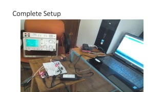
Complete Setup
Rectifier Circuit
MOSFET Bridge Circuit
Control Circuit using Arduino
Gate Trigger Pulse
3 level Inverter waveform on CRO
dSpace 1104
Specification of DS1104 R&D Controller Board
Parameter Characteristics
Processor MPC8240 processor with PPC603e core and on-chip
peripherals
• 64-bit floating-point processor
• 250 MHz CPU
• 2 x 16 KB cache; on-chip
• On-chip PCI bridge (33 MHz)
Memory Global memory: 32 MB SDRAM
• Flash memory: 8 MB
ADC
1 x 16-bit ADC with mux
4 x 12-bit ADC
5 ADC channels (1 x 16-bit + 4 x 12-bit) can be
sampled simultaneous
• 16-bit resolution
• ±10 V input voltage range
• 2μs conversion time
• 12-bit resolution
• ±10 V input voltage range
• 800 ns conversion time
Slave DSP subsystem • Texas Instruments TMS320F240 DSP
• 16-bit fixed-point processor
• 20 MHz clock frequency
• 64 K x 16 external program memory
• 28 K x 16 external data memory
• 4 K x 16 dual-port memory for communication
• 16 K x 16 flash memory
• 1 x 3-phase PWM output
• 4 x 1-phase PWM output
• ±13 mA maximum output current
Host interface • 32-bit PCI host interface
• 5VPCI slot
• 33MHz±5 %
Power supply • +5 V ±5 %, 2.5 A
• +12 V ±5 %, 0.3 A
Power consumption 18.5 W
Real Time System Validation using Hardware in Loop (HIL) Digital Platform
Parameter Settings for (a) ADC, (b) ADC Multiplexed and (c) PWM Blocks
(a)
(b)
(c)
Block Diagram
Peripheral Component Interconnect Bus (PCI Bus)
MPPT of a PV System
Real Time System Validation using Hardware in Loop (HIL) Digital Platform
MicroLabBox, with over 100 I/O channels of various types for applications in
robotics, medical engineering, electric drives, renewable energy, consumer
appliances, industrial products, automotive engineering, and aerospace
What is Real Time Simulation?
Simulation execution happens in synchronism
with wall clock time or real time
Why real time simulation?
To exchange information with physical components.
How real time simulation is done?
• The complexity of the plant under control is included in test
and development by adding a mathematical
representation of all related dynamic systems. These
mathematical representations are referred to as the “plant
simulation”. The embedded system to be tested interacts
with this plant simulation.
• It allows testing of an unlimited number of short circuits and
other transients (e.g. fault transients), as well as regular
transients in the power system. Something that is impractical
to do on the actual system.
• Virtual, highly realistic, real-time models of the hardware
(microgrid testbed) enable testing high power systems
without the dangers and costs involved with testing high
power.
35
Real Time Simulation Applications
For time critical studies!
1) Controller design, test and interface
2) Closed loop test of intelligent electronic devices
3) SCADA system studies; Operator training
4) Modern micro-grid/smart grid studies
5) Special Protection Schemes – design and test
Testing controllers using dSpace for grid
interfaces, electric drives, and power
electronics
Real Time System Validation using Hardware in Loop (HIL) Digital Platform
38
OPAL-RT HIL – General Architecture
The hardware that perform real time simulation consists of
Computational Units: CPU & FPGA
Interfacing Units: Analog & Digital I/O cards, serial ports, PCI slots
Hardware = Standard Intel PC + Xilinx FPGA + Interfacing units
Standard Intel PC
with Motherboard,
hard-disk, RAM, CPU
Xilinx
FPGA
Interfacing unit with
Analog & Digital I/Os,
serial ports, PCI slots etc.
OPAL-RT Real Time Simulation Hardware
PC with MATLAB/ SIMULINK
Opal-RT HIL Box
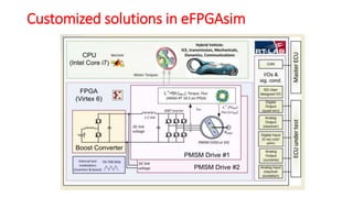
Customized solutions in eFPGAsim
Limitations of SPS for achieving real-time simulation
• SPS generates a unique matrix for State-Space equations, even if the matrix
is sparsed
• Results in higher computation time
• SPS recomputes system matrix in the real-time loop each time there is a
switch change conduction state (On/Off)
• Results in overruns each time a different topology occurs
ARTEMIS for Real-Time Simulation of Power Systems
SimPowerSystem (SPS) presentation
41
• ARTEMIS takes advantage of the sparse matrix properties to optimize the
computation time : In SPS and ARTEMIS, each independent sub-circuit has its own
smaller set of ABCD state-space equations
• FASTER iteration. (SPS S-functions are not sparsity-optimized) switches located on
different sub-networks are pre-computed independently
ARTEMIS for Real-Time Simulation of Power Systems
42
• ARTEMIS accuracy : ARTEMIS
solvers are designed to improve the
accuracy of simulation of power
system at large time steps
• Simulink signals are updated at next sample time
• RT-EVENTS too, but it keeps transition information (in the
time stamp)
• Accuracy of gate pulses is highly increased for the same
time-step
RT-Events for PWM generation
RT-Events concepts
44
Simulink
RT-Events
Typhoon HIL
Real Time System Validation using Hardware in Loop (HIL) Digital Platform
Questions, Comments?
Shimi.reji@gmail.com
www.slideshare.net/shimireji
9417588987
Thanks
System Validation using
Hardware
Dr. Shimi S.L
Assistant Professor
Electrical Engineering Dept
NITTTR, Chandigarh

More Related Content

PPTX
AUToSAR introduction
PPTX
Embedded Systems
PPTX
Understanding Flash Bootloader Software and Automotive ECU Reprogramming
PDF
Microcontroller part 1
PPTX
Autosar fundamental
PDF
Automotive embedded systems part8 v1
PPTX
Autosar MCAL (Microcontroller Abstraction Layer)
PPTX
UDS: Vehicle Diagnostics in AUTOSAR Software Architecture
AUToSAR introduction
Embedded Systems
Understanding Flash Bootloader Software and Automotive ECU Reprogramming
Microcontroller part 1
Autosar fundamental
Automotive embedded systems part8 v1
Autosar MCAL (Microcontroller Abstraction Layer)
UDS: Vehicle Diagnostics in AUTOSAR Software Architecture

What's hot (20)

PDF
Adaptive AUTOSAR - The New AUTOSAR Architecture
PPT
Introduction to embedded systems
PPTX
Over-the-air (OTA) updates and the Connected car
PPT
Design of embedded systems
PDF
Autosar Basics hand book_v1
PDF
C programming session5
PPTX
Hardware Software Codesign
PPTX
Communication stack
PPTX
What is AUTOSAR Communiation Stack
PPT
Hard ip based SoC design
PDF
DSP Processor
PDF
Multicore and AUTOSAR
PDF
Technical slides tia_portal_v15_en
PPT
Fpga Knowledge
PPTX
CONNECTED vehicle ECU.pptx
PPTX
HDL (hardware description language) presentation
PPT
Role of CAN BUS in automotives
PDF
What is AUTOSAR MCAL? Learn about the software module architecture and device...
PPTX
STM32 Microcontroller Clocks and RCC block
Adaptive AUTOSAR - The New AUTOSAR Architecture
Introduction to embedded systems
Over-the-air (OTA) updates and the Connected car
Design of embedded systems
Autosar Basics hand book_v1
C programming session5
Hardware Software Codesign
Communication stack
What is AUTOSAR Communiation Stack
Hard ip based SoC design
DSP Processor
Multicore and AUTOSAR
Technical slides tia_portal_v15_en
Fpga Knowledge
CONNECTED vehicle ECU.pptx
HDL (hardware description language) presentation
Role of CAN BUS in automotives
What is AUTOSAR MCAL? Learn about the software module architecture and device...
STM32 Microcontroller Clocks and RCC block
Ad

Similar to Real Time System Validation using Hardware in Loop (HIL) Digital Platform (20)

PDF
OPAL-RT RT13 Conference: Rapid control prototyping solutions for power electr...
PPTX
Microcontroller from basic_to_advanced
PPTX
Overview of Microcontroller and ATMega32 microcontroller
PDF
Bioinstrumentation Deploying AMS Technology
PPT
An Overview on Programmable System on Chip: PSoC-5
PPT
Embedded systemsc
PPT
8051 Presentation
PPT
FPGA_prototyping proccesing with conclusion
PPT
An Overview of LPC2101/02/03
PPTX
Arduino_Beginner.pptx
PPTX
Embedded system design using arduino
PPTX
CHAPTER1.pptx ON 8051 MICROCONTROLLER INTRODUCTION CHAPTER
PPTX
EMBEDDED SYSTEM BASICS
PPT
PIC Introduction and explained in detailed
PDF
Research Inventy : International Journal of Engineering and Science is publis...
PDF
Research Inventy: International Journal of Engineering and Science
PDF
microcontroller 8051 17.07.2023.pdf
PPT
Embedded System Introduction and applications.ppt
PPT
Embedded System intro Embedded System intro.ppt
PPT
Computing systems are everywhere Most of us think of “desktop” computers PC’s...
OPAL-RT RT13 Conference: Rapid control prototyping solutions for power electr...
Microcontroller from basic_to_advanced
Overview of Microcontroller and ATMega32 microcontroller
Bioinstrumentation Deploying AMS Technology
An Overview on Programmable System on Chip: PSoC-5
Embedded systemsc
8051 Presentation
FPGA_prototyping proccesing with conclusion
An Overview of LPC2101/02/03
Arduino_Beginner.pptx
Embedded system design using arduino
CHAPTER1.pptx ON 8051 MICROCONTROLLER INTRODUCTION CHAPTER
EMBEDDED SYSTEM BASICS
PIC Introduction and explained in detailed
Research Inventy : International Journal of Engineering and Science is publis...
Research Inventy: International Journal of Engineering and Science
microcontroller 8051 17.07.2023.pdf
Embedded System Introduction and applications.ppt
Embedded System intro Embedded System intro.ppt
Computing systems are everywhere Most of us think of “desktop” computers PC’s...
Ad

More from SHIMI S L (15)

PPTX
Preparation for NBA
PPTX
NBA - laboratories
PPTX
PPTX
Nba co attainment
PDF
Selective harmonic elimination in a solar powered multilevel inverter
PDF
MPPT of a solar system
PPTX
Fuzzy Logic and Neural Network
PPTX
Genetic Algorithm
PPTX
Advance control theory
PPT
Flexible AC Transmission (FACTS)
PPT
Solar energy application for electric power generation
PPT
Solid State Control of Electric Drive
PPTX
Arduino
PPTX
Choppers and cycloconverters
PPT
Thyristor technology
Preparation for NBA
NBA - laboratories
Nba co attainment
Selective harmonic elimination in a solar powered multilevel inverter
MPPT of a solar system
Fuzzy Logic and Neural Network
Genetic Algorithm
Advance control theory
Flexible AC Transmission (FACTS)
Solar energy application for electric power generation
Solid State Control of Electric Drive
Arduino
Choppers and cycloconverters
Thyristor technology

Recently uploaded (20)

PDF
Unit1 - AIML Chapter 1 concept and ethics
PDF
VTU IOT LAB MANUAL (BCS701) Computer science and Engineering
PPTX
Wireless sensor networks (WSN) SRM unit 2
PPTX
BBOC407 BIOLOGY FOR ENGINEERS (CS) - MODULE 1 PART 1.pptx
PPTX
SE unit 1.pptx aaahshdhajdviwhsiehebeiwheiebeiev
PPT
UNIT-I Machine Learning Essentials for 2nd years
PDF
Present and Future of Systems Engineering: Air Combat Systems
PPTX
Micro1New.ppt.pptx the mai themes of micfrobiology
PDF
VSL-Strand-Post-tensioning-Systems-Technical-Catalogue_2019-01.pdf
PDF
Project_Mgmt_Institute_-Marc Marc Marc .pdf
PPT
Programmable Logic Controller PLC and Industrial Automation
PPTX
Environmental studies, Moudle 3-Environmental Pollution.pptx
PDF
Cryptography and Network Security-Module-I.pdf
PDF
AIGA 012_04 Cleaning of equipment for oxygen service_reformat Jan 12.pdf
PDF
Research on ultrasonic sensor for TTU.pdf
PDF
Computer organization and architecuture Digital Notes....pdf
PDF
Unit I -OPERATING SYSTEMS_SRM_KATTANKULATHUR.pptx.pdf
PDF
Designing Fault-Tolerant Architectures for Resilient Oracle Cloud ERP and HCM...
PDF
Computer System Architecture 3rd Edition-M Morris Mano.pdf
PPTX
Module1.pptxrjkeieuekwkwoowkemehehehrjrjrj
Unit1 - AIML Chapter 1 concept and ethics
VTU IOT LAB MANUAL (BCS701) Computer science and Engineering
Wireless sensor networks (WSN) SRM unit 2
BBOC407 BIOLOGY FOR ENGINEERS (CS) - MODULE 1 PART 1.pptx
SE unit 1.pptx aaahshdhajdviwhsiehebeiwheiebeiev
UNIT-I Machine Learning Essentials for 2nd years
Present and Future of Systems Engineering: Air Combat Systems
Micro1New.ppt.pptx the mai themes of micfrobiology
VSL-Strand-Post-tensioning-Systems-Technical-Catalogue_2019-01.pdf
Project_Mgmt_Institute_-Marc Marc Marc .pdf
Programmable Logic Controller PLC and Industrial Automation
Environmental studies, Moudle 3-Environmental Pollution.pptx
Cryptography and Network Security-Module-I.pdf
AIGA 012_04 Cleaning of equipment for oxygen service_reformat Jan 12.pdf
Research on ultrasonic sensor for TTU.pdf
Computer organization and architecuture Digital Notes....pdf
Unit I -OPERATING SYSTEMS_SRM_KATTANKULATHUR.pptx.pdf
Designing Fault-Tolerant Architectures for Resilient Oracle Cloud ERP and HCM...
Computer System Architecture 3rd Edition-M Morris Mano.pdf
Module1.pptxrjkeieuekwkwoowkemehehehrjrjrj

Real Time System Validation using Hardware in Loop (HIL) Digital Platform

  • 1. Real Time System Validation using Hardware in Loop (HIL) Digital Platform Dr. Shimi S.L Assistant Professor Electrical Engineering Dept NITTTR, Chandigarh
  • 2. Intelligent Controllers Smart Sensors – Not Only Intelligent, but Adaptable Intelligent Actuators Plant
  • 3. Is Smart & Flexible Sensors Possible ?
  • 4. Microprocessor Microcontroller CPU-on-a-Chip Computer-on-a-Chip General Purpose Task Specific Used in Computer Systems Used in Embedded Systems Memory and I/O components are interfaced externally On-chip Memory and I/O Components Since external components interfaced, so the whole system is larger and costly Since On-chip components, so system is smaller and cheaper In Microprocessor based system, Instruction and data are stored in same memory module In Microcontroller based system, program memory and data memory are separate Microprocessor “CPU-on-a-Chip” Microcontroller “Computer-on-a-Chip”
  • 6. CB - Connection Blocks SB - Switching Block CLB - Configurable Logic Block LUT - Look-Up-Table
  • 8. Most Popular Controllers • Atmel  8051  AVR • Microchip  PIC16F877 • ARM  ARM7  ARM9  ARM Cortex and many more…….
  • 9. Architecture-ARM Microcontroller Interrupt Address Address register Incrementer Read register 32 bit register bank 32 Bit ALU register bank Read register Instruction Pipeline Instruction decoder Debug control Interrupt Control Incrementer Data Address Data Bus Data bus Instruction Address Instruction data A Bus B Bus PCBus Write register
  • 10. • Software • ARM C/C++ Compiler (armcc) Development Platform-ARM • Hardware – One DBGU serial communication port – One ZIGBEE extension connector – One JTAG debug interface – Five user- input push buttons – One Wake-UP input push button – One Reset Push Button – One Battery Socket for two AAA batteries – One 400 segments dot matrix LCD
  • 11. Controller 8051 PIC ARM Bit Addressable 8 bit 8,12,14 & 16 bit 16 & 32 Bit Max. crystal Freq. (MHz) 4-16 MHz Up to 80 MHz Up to 400 MHz Operating voltage (volts) 1-5V 1.5 to 5 V 1- 5V Flash 0.5K - 384K Up to 512K 16k to 2M Cache ---- ---- 2x4k - 16k + 8k Peripherals available USART, SPI, USB, I2C USART, SPI, I2C, ADC, DAC, USB, Ethernet, CAN USART, SPI, I2C, USB, ADC, DAC, Video Decoder, Image Sensor Interface Comparison
  • 12. Debug code Including external I/O stimulus Order HW boards/parts SW comp, debugger Build Prototype Enter Specifications Select Best Part Configure core, peripherals & Auto- generate Code Customize main loop/events integrate libraries & Generate Object Microcontroller Development Process
  • 14. ICSP (In-Circuit Serial Programming)
  • 15. Microcontroller ATmega328 Operating Voltage 5V Input Voltage (recommended) 7-12V Input Voltage (limits) 6-20V Digital I/O Pins 14 (of which 6 provide PWM output) Analog Input Pins 6 DC Current per I/O Pin 40 mA DC Current for 3.3V Pin 50 mA Flash Memory 32 KB (ATmega328) of which 0.5 KB used by bootloader SRAM 2 KB (ATmega328) EEPROM 1 KB (ATmega328) Clock Speed 16 MHz
  • 22. 3 level Inverter waveform on CRO
  • 24. Specification of DS1104 R&D Controller Board Parameter Characteristics Processor MPC8240 processor with PPC603e core and on-chip peripherals • 64-bit floating-point processor • 250 MHz CPU • 2 x 16 KB cache; on-chip • On-chip PCI bridge (33 MHz) Memory Global memory: 32 MB SDRAM • Flash memory: 8 MB ADC 1 x 16-bit ADC with mux 4 x 12-bit ADC 5 ADC channels (1 x 16-bit + 4 x 12-bit) can be sampled simultaneous • 16-bit resolution • ±10 V input voltage range • 2μs conversion time • 12-bit resolution • ±10 V input voltage range • 800 ns conversion time Slave DSP subsystem • Texas Instruments TMS320F240 DSP • 16-bit fixed-point processor • 20 MHz clock frequency • 64 K x 16 external program memory • 28 K x 16 external data memory • 4 K x 16 dual-port memory for communication • 16 K x 16 flash memory • 1 x 3-phase PWM output • 4 x 1-phase PWM output • ±13 mA maximum output current Host interface • 32-bit PCI host interface • 5VPCI slot • 33MHz±5 % Power supply • +5 V ±5 %, 2.5 A • +12 V ±5 %, 0.3 A Power consumption 18.5 W
  • 27. Parameter Settings for (a) ADC, (b) ADC Multiplexed and (c) PWM Blocks (a) (b) (c)
  • 28. Block Diagram Peripheral Component Interconnect Bus (PCI Bus)
  • 29. MPPT of a PV System
  • 32. MicroLabBox, with over 100 I/O channels of various types for applications in robotics, medical engineering, electric drives, renewable energy, consumer appliances, industrial products, automotive engineering, and aerospace
  • 33. What is Real Time Simulation? Simulation execution happens in synchronism with wall clock time or real time Why real time simulation? To exchange information with physical components.
  • 34. How real time simulation is done? • The complexity of the plant under control is included in test and development by adding a mathematical representation of all related dynamic systems. These mathematical representations are referred to as the “plant simulation”. The embedded system to be tested interacts with this plant simulation. • It allows testing of an unlimited number of short circuits and other transients (e.g. fault transients), as well as regular transients in the power system. Something that is impractical to do on the actual system. • Virtual, highly realistic, real-time models of the hardware (microgrid testbed) enable testing high power systems without the dangers and costs involved with testing high power.
  • 35. 35 Real Time Simulation Applications For time critical studies! 1) Controller design, test and interface 2) Closed loop test of intelligent electronic devices 3) SCADA system studies; Operator training 4) Modern micro-grid/smart grid studies 5) Special Protection Schemes – design and test
  • 36. Testing controllers using dSpace for grid interfaces, electric drives, and power electronics
  • 38. 38 OPAL-RT HIL – General Architecture The hardware that perform real time simulation consists of Computational Units: CPU & FPGA Interfacing Units: Analog & Digital I/O cards, serial ports, PCI slots Hardware = Standard Intel PC + Xilinx FPGA + Interfacing units Standard Intel PC with Motherboard, hard-disk, RAM, CPU Xilinx FPGA Interfacing unit with Analog & Digital I/Os, serial ports, PCI slots etc. OPAL-RT Real Time Simulation Hardware
  • 39. PC with MATLAB/ SIMULINK Opal-RT HIL Box
  • 41. Limitations of SPS for achieving real-time simulation • SPS generates a unique matrix for State-Space equations, even if the matrix is sparsed • Results in higher computation time • SPS recomputes system matrix in the real-time loop each time there is a switch change conduction state (On/Off) • Results in overruns each time a different topology occurs ARTEMIS for Real-Time Simulation of Power Systems SimPowerSystem (SPS) presentation 41
  • 42. • ARTEMIS takes advantage of the sparse matrix properties to optimize the computation time : In SPS and ARTEMIS, each independent sub-circuit has its own smaller set of ABCD state-space equations • FASTER iteration. (SPS S-functions are not sparsity-optimized) switches located on different sub-networks are pre-computed independently ARTEMIS for Real-Time Simulation of Power Systems 42
  • 43. • ARTEMIS accuracy : ARTEMIS solvers are designed to improve the accuracy of simulation of power system at large time steps
  • 44. • Simulink signals are updated at next sample time • RT-EVENTS too, but it keeps transition information (in the time stamp) • Accuracy of gate pulses is highly increased for the same time-step RT-Events for PWM generation RT-Events concepts 44 Simulink RT-Events
  • 49. System Validation using Hardware Dr. Shimi S.L Assistant Professor Electrical Engineering Dept NITTTR, Chandigarh