3
Most read
5
Most read
6
Most read
1
DEPARTMENT OF ELECTRONICS & COMMUNICATION
ENGINEERING
PONDICHERRY UNIVERSITY
SMART TRAFFIC LIGHT CONTROLLER USING
VERILOG
GUIDED BY
PROF. Dr. P. SAMUNDISWARI
Dept. Of Electronics Engineering
PRESENTED BY
BEULAH .A
VAISHALI .K
M.Tech (ECE)-Ist yr
2
CONTENTS
S. NO. TOPIC PAGE NO.
1 OBJECTIVE 3
2 INTRODUCTION 3
3 BLOCK DIAGRAM 4
4 WORKING PRINCIPLE 5
5 STATE DIAGRAM 6
6 CODE 7
7 TEST BENCH 10
8 SIMULATION OUTPUT 11-15
9 ADVANTAGES AND DISADVANTAGES 15 -16
10 CONCLUSION 16
11 REFERENCES 16
3
OBJECTIVE:
• The main aim of the project is to design a two way traffic light controller
using verilog.
• One with the help of timing mechanism and other by the help of detector or
sensor.
SOFTWARE USED:
• Xilinx 14.7
• Verilog: C like HDL is easier to comprehend and saves design time since the
syntax is more concise that VHDL
INTRODUCTION:
• In general, many traffic lights are operates on a timing mechanism that
changes the light after given time interval.
• The traffic light system consists of three important parts, in that traffic light
controller is first one, because of it represent brain of the traffic system.
• The second part is the signal visualization or in simple words is signal face.
• The third part is the detector or sensor.
TRAFFIC LIGHTS:
• An intelligent traffic light system senses the presence or absence of vehicles
and reacts accordingly.
• The idea behind intelligent traffic systems is that drivers will not spend
unnecessary time waiting for the traffic lights to change.
• In the traffic light control system, the main controller, control circuit,
counter, timer, decoder, clock signal generator, decoder drive circuit and
digital display decoder drive circuit are needed to complete the whole
process of controlling the traffic light.
4
BLOCK DIAGRAM:
EXPANDED RTL VIEW:
5
WORKING PRINCIPLE;
• The main road's lights are always green for the major traffic to pass.
• The main road's lights turn red only when there is a car on either side of the
side road for a period of time.
• When detector detect the vehicles, only then the lights on the side road turn
from red->green while the main road's lights turn from green->yellow->red.
• After the given interval of time, lights on the main road turns to red-
>yellow->green and the side road turns from green->red.
• In the timer part, there are three things one is the short time pulse (TS) and
6
the long time pulse (TL) and the last is a response to start the timer (ST)
signal.
STATE DIAGRAM:
• The main road will be green until no cars are found and it remains in state
S0.
• When long time expires and cars found the transition from S0 to S1 takes
place.
• When the short time interval expires it transit from S1 to S2.
• When the long time interval doesn't expire and cars are detected it will in the
state S2.
• When the long time expires and no more cars detected it transit from S2 to
S3.
• When the short interval expires it transit from S3 to S0 and the cycle
continues.
7
CODE:
MAIN MODULE:
`timescale 1ns / 1ps
module main(
output MR,
output MY,
output MG,
output SR,
output SY,
output SG,
input reset,
input C,
input Clk
);
timer part1(TS, TL, ST, Clk);
fsm part2(MR, MY, MG, SR, SY, SG, ST, TS, TL, C, reset, Clk);
endmodule
TIMER MODULE:
`timescale 1ns / 1ps
module timer(
output TS,
output TL,
input ST,
input Clk
);
integer value;
8
assign TS=(value>=4);
assign TL=(value>=14);
always@(posedge ST or posedge Clk)
begin
if(ST==1)begin
value=0;
end
else begin
value=value+1;
end
end
endmodule
FSM MODULE:
`timescale 1ns / 1ps
module fsm(
output MR,
output MY,
output MG,
output SR,
output SY,
output SG,
output ST,
input TS,
input TL,
input C,
input reset,
9
input Clk
);
reg [6:1] state;
reg ST;
parameter mainroadgreen= 6'b001100;
parameter mainroadyellow= 6'b010100;
parameter sideroadgreen= 6'b100001;
parameter sideroadyellow= 6'b100010;
assign MR = state[6];
assign MY = state[5];
assign MG = state[4];
assign SR = state[3];
assign SY = state[2];
assign SG = state[1];
initial begin state = mainroadgreen; ST = 0; end
always @(posedge Clk)
begin
if (reset)
begin state = mainroadgreen; ST = 1; end
else
begin
ST = 0;
case (state)
mainroadgreen:
if (TL & C) begin state = mainroadyellow; ST = 1; end
mainroadyellow:
10
if (TS) begin state = sideroadgreen; ST = 1; end
sideroadgreen:
if (TL | !C) begin state = sideroadyellow; ST = 1; end
sideroadyellow:
if (TS) begin state = mainroadgreen; ST = 1; end
endcase
end
end
endmodule
TEST BENCH:
`timescale 1ns / 1ps
module fsm_test;
// Inputs
reg TS; reg TL; reg C;reg reset; reg Clk;
// Outputs
wire MR; wire MY; wire MG; wire SR; wire SY; wire SG;
wire ST;
// Instantiate the Unit Under Test (UUT)
fsm uut (
.MR(MR), .MY(MY), .MG(MG), .SR(SR), .SY(SY), .SG(SG), .ST(ST),
.TS(TS), .TL(TL), .C(C),
.reset(reset), .Clk(Clk)
);
initial begin
// Initialize Inputs
TS = 0;TL = 0;C = 0;reset = 1;
11
Clk = 0;
#100; TS=0;TL=1;C=1;reset=0;
#100; TS=0;TL=0;C=0;reset=1;
#100; TS=1;TL=1;C=0;reset=0;
#100;
end
always
begin
#100
Clk=~Clk;
end
endmodule
SIMULATION OUTPUT:
12
13
DEVICE UTILIZATION SUMMARY:
14
HDL SYNTHESIS REPORT:
15
ADVANTAGES:
• Traffic signals help for movement of traffic securely without any collision.
• The drivers will not spend unnecessary time waiting for the traffic lights to
change.
• Traffic control by signals is accurate and economical as compared to traffic
police control.
16
DISADVANTAGES :
• During signals breakdown, there are serious and wide-spread traffic
difficulties during peak hours.
CONCLUSION;
• In this project we introduced detector based technology for traffic control.
• We conclude that it provides powerful solution to improve existing system
with the new smart traffic light controller.
FUTURE SCOPE :
• Blinking of lights according to the traffic level present in the road can be
added.
• Managing traffic when any emergency vehicle come can also be introduced.
For example ambulance.
REFERENCES:
• Ali Qureshi .M, Abdul Aziz, “A Verilog Model of Traffic Control System
using Mealy State Machines” in DOI:10.7763/IJCEE.2012.V4.521
• Swetha Reddy.K, Shabarinath .B.B, “timing and synchronization for explicit
FSM based traffic light controller”, Published 2019
• Owmya .B, ”An Advanced Traffic Light Controller using Verilog HDL”,
Published 2017

More Related Content

DOCX
design of FPGA based traffic light controller system
PDF
Biology For Engineers Module 3 / HUMAN ORGAN SYSTEMS AND BIO-DESIGNS - 2
PDF
Energy management
PDF
Phasor Measurement Unit (PMU)
PDF
Particle in One-Dimensional Infinite potential well (box)
PDF
Solutions control system sengineering by normannice 6ed 130502172814-phpapp02
PPTX
Four way traffic light conrol using Verilog
PPTX
alarm clock
design of FPGA based traffic light controller system
Biology For Engineers Module 3 / HUMAN ORGAN SYSTEMS AND BIO-DESIGNS - 2
Energy management
Phasor Measurement Unit (PMU)
Particle in One-Dimensional Infinite potential well (box)
Solutions control system sengineering by normannice 6ed 130502172814-phpapp02
Four way traffic light conrol using Verilog
alarm clock

What's hot (20)

PDF
Traffic light controller with verilog
PPT
design of FPGA based traffic light controller system
DOCX
HDL Implementation of Vending Machine Report with Verilog Code
PDF
Vlsi Summer training report pdf
PPTX
DIgital clock using verilog
PPSX
VLSI Testing Techniques
DOCX
Design of Elevator Controller using Verilog HDL
PPT
DOCX
Gate Diffusion Input Technology (Very Large Scale Integration)
PPTX
Modules and ports in Verilog HDL
PPTX
Serial Communication in 8051
PPTX
Design for testability and automatic test pattern generation
DOCX
UNIT-II CPLD & FPGA Architectures and Applications
PPT
I2C Protocol
PPTX
gate level modeling
PPTX
I2C Protocol
PDF
Synchronous Loadable Up and Down Counter
DOCX
Report on VLSI
PPTX
System partitioning in VLSI and its considerations
PPTX
Clock divider by 3
Traffic light controller with verilog
design of FPGA based traffic light controller system
HDL Implementation of Vending Machine Report with Verilog Code
Vlsi Summer training report pdf
DIgital clock using verilog
VLSI Testing Techniques
Design of Elevator Controller using Verilog HDL
Gate Diffusion Input Technology (Very Large Scale Integration)
Modules and ports in Verilog HDL
Serial Communication in 8051
Design for testability and automatic test pattern generation
UNIT-II CPLD & FPGA Architectures and Applications
I2C Protocol
gate level modeling
I2C Protocol
Synchronous Loadable Up and Down Counter
Report on VLSI
System partitioning in VLSI and its considerations
Clock divider by 3
Ad

Similar to Smart traffic light controller using verilog (20)

PPTX
MICROCONTROLLER_ VTU_8051 TIMERS AND SERIAL PORTSModule3.pptx
PDF
Digital timer
PPTX
INTERRUPT DRIVEN MULTIPLEXED 7 SEGMENT DIGITAL CLOCK
PDF
Timing notes 2006
PDF
PDF
Lecture 2 timers, pwm, state machine IN PIC
DOCX
Digital Alarm Clock (IC-TMS-8560)
PPTX
ANALOG AND DIGITAL ELECTRONICS unit 5
PDF
DFT Rules, set of rules with illustration
PDF
Get Programmable digital timer | Programmable timer switch | Cyclic Timer- GI...
PDF
432112393-Manual-Injecao-Mercedes-Bens-Detroit.pdf
DOCX
MODULE TITLE PROGRAMMABLE LOGIC CONTROLLERSTOPIC TITLE.docx
PPT
8051 ch9-950217
PDF
Unit3_all timer interfacing in microcontroller
PDF
Deep Explaination of STA_setupandholdchecks
PPT
ppt of Three phase fault analysis with auto reset for temporary fault and tri...
PDF
Introduction to automation
PDF
A multi phase decision on reliability growth with latent failure modes
PDF
DESIGN AND IMPLEMENTATION OF AREA AND POWER OPTIMISED NOVEL SCANFLOP
PPT
29317254-Standard-Single-Purpose-Processors-Peripherals.ppt
MICROCONTROLLER_ VTU_8051 TIMERS AND SERIAL PORTSModule3.pptx
Digital timer
INTERRUPT DRIVEN MULTIPLEXED 7 SEGMENT DIGITAL CLOCK
Timing notes 2006
Lecture 2 timers, pwm, state machine IN PIC
Digital Alarm Clock (IC-TMS-8560)
ANALOG AND DIGITAL ELECTRONICS unit 5
DFT Rules, set of rules with illustration
Get Programmable digital timer | Programmable timer switch | Cyclic Timer- GI...
432112393-Manual-Injecao-Mercedes-Bens-Detroit.pdf
MODULE TITLE PROGRAMMABLE LOGIC CONTROLLERSTOPIC TITLE.docx
8051 ch9-950217
Unit3_all timer interfacing in microcontroller
Deep Explaination of STA_setupandholdchecks
ppt of Three phase fault analysis with auto reset for temporary fault and tri...
Introduction to automation
A multi phase decision on reliability growth with latent failure modes
DESIGN AND IMPLEMENTATION OF AREA AND POWER OPTIMISED NOVEL SCANFLOP
29317254-Standard-Single-Purpose-Processors-Peripherals.ppt
Ad

More from VaishaliVaishali14 (8)

PPTX
Simulation of speech recognition using correlation method on matlab software
PPTX
SIMULATION OF AN ELECTRONIC DICE CIRCUIT USING LEDs IN PROTEUS SOFTWARE
PPTX
PERFORMANCE ANALYSIS OF 2*2 MIMO CHANNEL USING ZF EQUALIZER
PPTX
LINE OF SIGHT PROPAGATION
PPTX
Linear equalizations and its variations
PPTX
Optical heterodyne detection
PDF
Simulation of handoff performance using matlab
PPTX
CMOS LOGIC STRUCTURES
Simulation of speech recognition using correlation method on matlab software
SIMULATION OF AN ELECTRONIC DICE CIRCUIT USING LEDs IN PROTEUS SOFTWARE
PERFORMANCE ANALYSIS OF 2*2 MIMO CHANNEL USING ZF EQUALIZER
LINE OF SIGHT PROPAGATION
Linear equalizations and its variations
Optical heterodyne detection
Simulation of handoff performance using matlab
CMOS LOGIC STRUCTURES

Recently uploaded (20)

PDF
SEH5E Unveiled: Enhancements and Key Takeaways for Certification Success
PDF
[jvmmeetup] next-gen integration with apache camel and quarkus.pdf
PDF
UEFA_Carbon_Footprint_Calculator_Methology_2.0.pdf
PPTX
Solar energy pdf of gitam songa hemant k
PPT
UNIT-I Machine Learning Essentials for 2nd years
PPTX
Module1.pptxrjkeieuekwkwoowkemehehehrjrjrj
PDF
MACCAFERRY GUIA GAVIONES TERRAPLENES EN ESPAÑOL
PDF
Computer organization and architecuture Digital Notes....pdf
PPTX
Cisco Network Behaviour dibuywvdsvdtdstydsdsa
PDF
Designing Fault-Tolerant Architectures for Resilient Oracle Cloud ERP and HCM...
PDF
MLpara ingenieira CIVIL, meca Y AMBIENTAL
PDF
UEFA_Embodied_Carbon_Emissions_Football_Infrastructure.pdf
PPTX
Micro1New.ppt.pptx the main themes if micro
PDF
VTU IOT LAB MANUAL (BCS701) Computer science and Engineering
PDF
Project_Mgmt_Institute_-Marc Marc Marc .pdf
PDF
AIGA 012_04 Cleaning of equipment for oxygen service_reformat Jan 12.pdf
PPTX
Design ,Art Across Digital Realities and eXtended Reality
PPTX
Principal presentation for NAAC (1).pptx
PPTX
CT Generations and Image Reconstruction methods
PPTX
BBOC407 BIOLOGY FOR ENGINEERS (CS) - MODULE 1 PART 1.pptx
SEH5E Unveiled: Enhancements and Key Takeaways for Certification Success
[jvmmeetup] next-gen integration with apache camel and quarkus.pdf
UEFA_Carbon_Footprint_Calculator_Methology_2.0.pdf
Solar energy pdf of gitam songa hemant k
UNIT-I Machine Learning Essentials for 2nd years
Module1.pptxrjkeieuekwkwoowkemehehehrjrjrj
MACCAFERRY GUIA GAVIONES TERRAPLENES EN ESPAÑOL
Computer organization and architecuture Digital Notes....pdf
Cisco Network Behaviour dibuywvdsvdtdstydsdsa
Designing Fault-Tolerant Architectures for Resilient Oracle Cloud ERP and HCM...
MLpara ingenieira CIVIL, meca Y AMBIENTAL
UEFA_Embodied_Carbon_Emissions_Football_Infrastructure.pdf
Micro1New.ppt.pptx the main themes if micro
VTU IOT LAB MANUAL (BCS701) Computer science and Engineering
Project_Mgmt_Institute_-Marc Marc Marc .pdf
AIGA 012_04 Cleaning of equipment for oxygen service_reformat Jan 12.pdf
Design ,Art Across Digital Realities and eXtended Reality
Principal presentation for NAAC (1).pptx
CT Generations and Image Reconstruction methods
BBOC407 BIOLOGY FOR ENGINEERS (CS) - MODULE 1 PART 1.pptx

Smart traffic light controller using verilog

  • 1. 1 DEPARTMENT OF ELECTRONICS & COMMUNICATION ENGINEERING PONDICHERRY UNIVERSITY SMART TRAFFIC LIGHT CONTROLLER USING VERILOG GUIDED BY PROF. Dr. P. SAMUNDISWARI Dept. Of Electronics Engineering PRESENTED BY BEULAH .A VAISHALI .K M.Tech (ECE)-Ist yr
  • 2. 2 CONTENTS S. NO. TOPIC PAGE NO. 1 OBJECTIVE 3 2 INTRODUCTION 3 3 BLOCK DIAGRAM 4 4 WORKING PRINCIPLE 5 5 STATE DIAGRAM 6 6 CODE 7 7 TEST BENCH 10 8 SIMULATION OUTPUT 11-15 9 ADVANTAGES AND DISADVANTAGES 15 -16 10 CONCLUSION 16 11 REFERENCES 16
  • 3. 3 OBJECTIVE: • The main aim of the project is to design a two way traffic light controller using verilog. • One with the help of timing mechanism and other by the help of detector or sensor. SOFTWARE USED: • Xilinx 14.7 • Verilog: C like HDL is easier to comprehend and saves design time since the syntax is more concise that VHDL INTRODUCTION: • In general, many traffic lights are operates on a timing mechanism that changes the light after given time interval. • The traffic light system consists of three important parts, in that traffic light controller is first one, because of it represent brain of the traffic system. • The second part is the signal visualization or in simple words is signal face. • The third part is the detector or sensor. TRAFFIC LIGHTS: • An intelligent traffic light system senses the presence or absence of vehicles and reacts accordingly. • The idea behind intelligent traffic systems is that drivers will not spend unnecessary time waiting for the traffic lights to change. • In the traffic light control system, the main controller, control circuit, counter, timer, decoder, clock signal generator, decoder drive circuit and digital display decoder drive circuit are needed to complete the whole process of controlling the traffic light.
  • 5. 5 WORKING PRINCIPLE; • The main road's lights are always green for the major traffic to pass. • The main road's lights turn red only when there is a car on either side of the side road for a period of time. • When detector detect the vehicles, only then the lights on the side road turn from red->green while the main road's lights turn from green->yellow->red. • After the given interval of time, lights on the main road turns to red- >yellow->green and the side road turns from green->red. • In the timer part, there are three things one is the short time pulse (TS) and
  • 6. 6 the long time pulse (TL) and the last is a response to start the timer (ST) signal. STATE DIAGRAM: • The main road will be green until no cars are found and it remains in state S0. • When long time expires and cars found the transition from S0 to S1 takes place. • When the short time interval expires it transit from S1 to S2. • When the long time interval doesn't expire and cars are detected it will in the state S2. • When the long time expires and no more cars detected it transit from S2 to S3. • When the short interval expires it transit from S3 to S0 and the cycle continues.
  • 7. 7 CODE: MAIN MODULE: `timescale 1ns / 1ps module main( output MR, output MY, output MG, output SR, output SY, output SG, input reset, input C, input Clk ); timer part1(TS, TL, ST, Clk); fsm part2(MR, MY, MG, SR, SY, SG, ST, TS, TL, C, reset, Clk); endmodule TIMER MODULE: `timescale 1ns / 1ps module timer( output TS, output TL, input ST, input Clk ); integer value;
  • 8. 8 assign TS=(value>=4); assign TL=(value>=14); always@(posedge ST or posedge Clk) begin if(ST==1)begin value=0; end else begin value=value+1; end end endmodule FSM MODULE: `timescale 1ns / 1ps module fsm( output MR, output MY, output MG, output SR, output SY, output SG, output ST, input TS, input TL, input C, input reset,
  • 9. 9 input Clk ); reg [6:1] state; reg ST; parameter mainroadgreen= 6'b001100; parameter mainroadyellow= 6'b010100; parameter sideroadgreen= 6'b100001; parameter sideroadyellow= 6'b100010; assign MR = state[6]; assign MY = state[5]; assign MG = state[4]; assign SR = state[3]; assign SY = state[2]; assign SG = state[1]; initial begin state = mainroadgreen; ST = 0; end always @(posedge Clk) begin if (reset) begin state = mainroadgreen; ST = 1; end else begin ST = 0; case (state) mainroadgreen: if (TL & C) begin state = mainroadyellow; ST = 1; end mainroadyellow:
  • 10. 10 if (TS) begin state = sideroadgreen; ST = 1; end sideroadgreen: if (TL | !C) begin state = sideroadyellow; ST = 1; end sideroadyellow: if (TS) begin state = mainroadgreen; ST = 1; end endcase end end endmodule TEST BENCH: `timescale 1ns / 1ps module fsm_test; // Inputs reg TS; reg TL; reg C;reg reset; reg Clk; // Outputs wire MR; wire MY; wire MG; wire SR; wire SY; wire SG; wire ST; // Instantiate the Unit Under Test (UUT) fsm uut ( .MR(MR), .MY(MY), .MG(MG), .SR(SR), .SY(SY), .SG(SG), .ST(ST), .TS(TS), .TL(TL), .C(C), .reset(reset), .Clk(Clk) ); initial begin // Initialize Inputs TS = 0;TL = 0;C = 0;reset = 1;
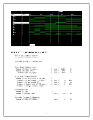
  • 11. 11 Clk = 0; #100; TS=0;TL=1;C=1;reset=0; #100; TS=0;TL=0;C=0;reset=1; #100; TS=1;TL=1;C=0;reset=0; #100; end always begin #100 Clk=~Clk; end endmodule SIMULATION OUTPUT:
  • 12. 12
  • 15. 15 ADVANTAGES: • Traffic signals help for movement of traffic securely without any collision. • The drivers will not spend unnecessary time waiting for the traffic lights to change. • Traffic control by signals is accurate and economical as compared to traffic police control.
  • 16. 16 DISADVANTAGES : • During signals breakdown, there are serious and wide-spread traffic difficulties during peak hours. CONCLUSION; • In this project we introduced detector based technology for traffic control. • We conclude that it provides powerful solution to improve existing system with the new smart traffic light controller. FUTURE SCOPE : • Blinking of lights according to the traffic level present in the road can be added. • Managing traffic when any emergency vehicle come can also be introduced. For example ambulance. REFERENCES: • Ali Qureshi .M, Abdul Aziz, “A Verilog Model of Traffic Control System using Mealy State Machines” in DOI:10.7763/IJCEE.2012.V4.521 • Swetha Reddy.K, Shabarinath .B.B, “timing and synchronization for explicit FSM based traffic light controller”, Published 2019 • Owmya .B, ”An Advanced Traffic Light Controller using Verilog HDL”, Published 2017